Surface mounted electrical component

Inactive Publication Date: 2005-11-22
WECO ELECTRICAL CONNECTORS
View PDF9 Cites 5 Cited by
  • Summary
  • Abstract
  • Description
  • Claims
  • Application Information

AI Technical Summary

Benefits of technology

[0006]It is the purpose of the present invention to provide electrical components which can be more securely anchored to PCB's. More particularly, it is the purpose of the present invention to provide electrical components with anchor elements constructed and mounted so as to allow more secure connection between electrical components and PCB's, the anchor e

Problems solved by technology

However, the surface mount (SM) soldered joints between the connecting leads and the PCB are not very strong and can be easily broken by many types of force applied to the connector.
However, these fastening means have their own disadvantages.
The excessive force may however cause damage to the connectors.
Drilling of the PCB's may also be required to accommodate the additional mechanical fasteners which operation can increase the cost of assembly.
However, the anchor elements employed do not always make good contact with the soldering pads on the PCB since the bottoms o

Method used


Image

  • Surface mounted electrical component
  • Surface mounted electrical component
  • Surface mounted electrical component

Examples


Embodiment Construction

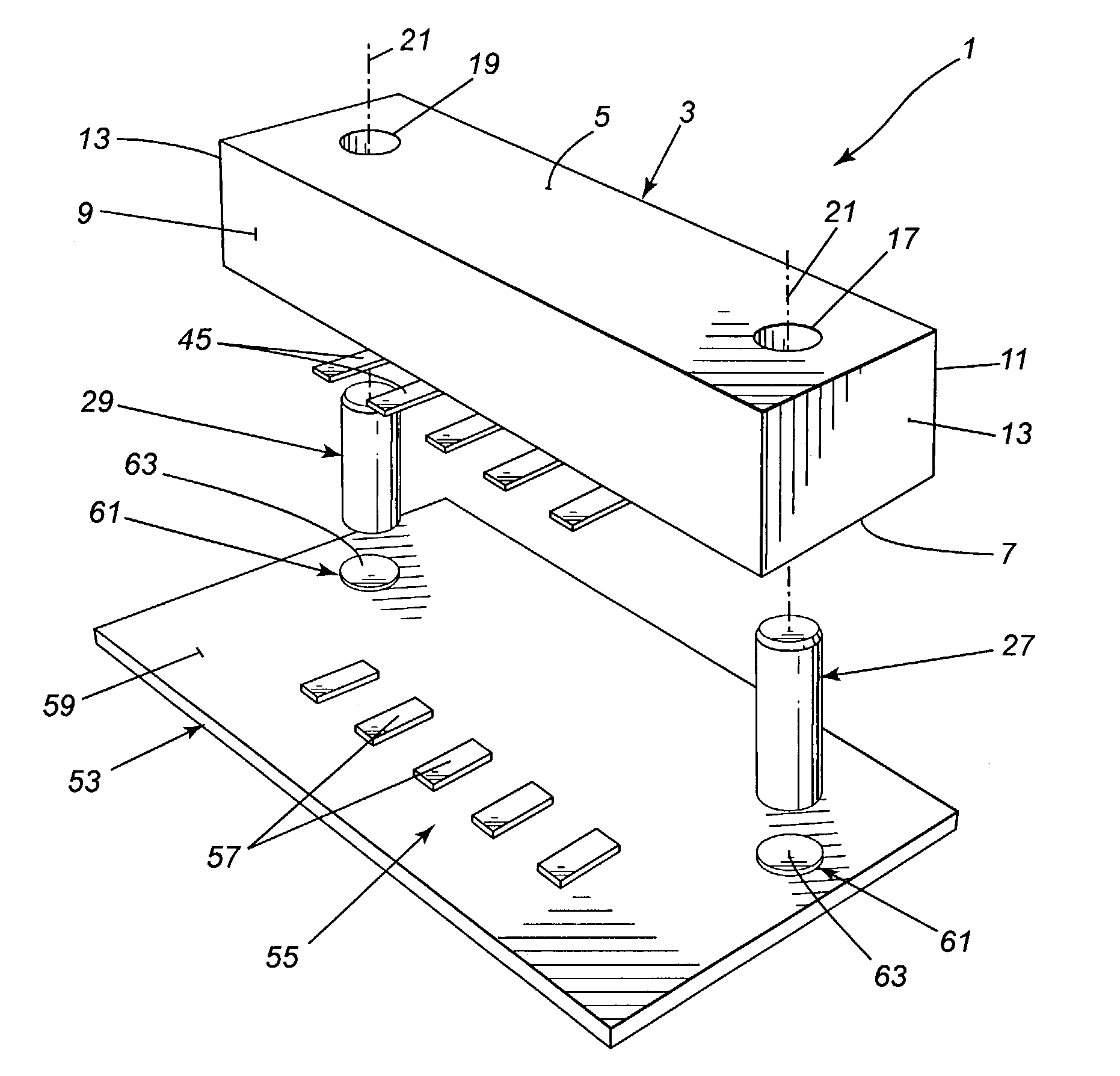
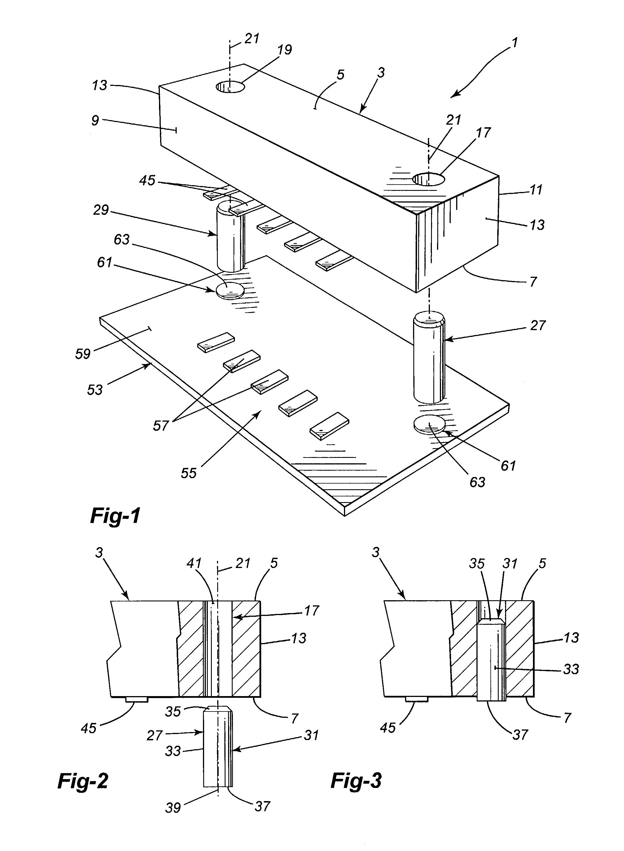
[0020]The electrical component of the present invention can be an electrical connector 1 as shown in FIG. 1. The electrical connector has a connector housing 3 made from insulating material, such as plastic, and has a generally parallelepiped shape with parallel top and bottom surfaces 5 and 7, parallel front and back surfaces 9 and 11 and parallel end surfaces 13.

[0021]The connector housing 3 has two apertures 17, 19, one adjacent each end 13 respectively of the housing. The apertures each receive a surface mount anchor element as will be described. The apertures 17, 19 are preferably cylindrical in shape and extend upwardly from the bottom surface 7 of the connector housing 3, the longitudinal axis 21 of the apertures at right angles to the bottom surface 7 of the housing. The apertures 17, 19 can extend through the housing 3 from the bottom surface 7 to the top surface 5, as shown. The apertures 17, 19 can however also be blind holes extending up from the bottom surface 7 of the ...


PUM


Abstract

An electrical component having an insulating housing with the housing having a bottom mounting surface and at least one anchor element receiving aperture extending up into the housing from the bottom surface of the housing. An anchor element, having a bottom end, is shaped and sized to be inserted into the aperture from the bottom of the housing, the element frictionally held by the housing in the aperture with the element projecting slightly from the aperture to have its bottom end spaced slightly from the bottom surface of the housing.
A method of assembling the electrical component having a housing with a bottom surface and an aperture for receiving an anchor element extending up into the housing from the bottom surface. The anchor element has at least a portion that is sized and shaped to frictionally engage the housing while in the aperture. The method comprises the step of inserting the anchor element into the aperture in the housing from the bottom surface of the housing and pressing the element into the aperture to frictionally engage the housing, the element pressed into the aperture until it projects only slightly from the housing below the bottom surface of the housing.
An anchor element for use in the above electrical component having a cylindrical shape with the upper portion of the element stepped down slightly in diameter from the bottom portion, the upper portion sized to snugly enter an aperture in a housing of an electrical connector, the bottom portion sized to frictionally engage the wall of the housing defining the aperture.

Description

BACKGROUND OF THE INVENTION[0001]1. Field of the Invention[0002]This invention is directed toward a surface mounted electrical component. The invention is also directed toward a method of assembling the electrical component. The invention is more particularly directed toward an electrical connector, adapted to be mounted on the top surface of a printed circuit board (PCB), and to a method of assembling the connector. The invention is further directed toward an anchor element forming part of the assembled electrical connector, the anchor element used in connecting the connector to a PCB.[0003]2. Description of the Related Art[0004]It is well known to mount an electrical component, such as an electrical connector, on the surface of a printed circuit board (PCB). The electrical connector is mounted on the surface of the PCB by soldering electrical connecting leads, located on the bottom of the connector, to the surface of the board, the connecting leads providing an electrical connecti...

Claims


Application Information

Patent Timeline
IPC IPC(8): H01R12/14H01R12/00H01R13/73H05K7/02H05K7/06H01R12/55
CPCH01R12/7064
Inventor XU, PEI REN
Owner WECO ELECTRICAL CONNECTORS
Why Eureka
Try Eureka