
Actuator

Inactive Publication Date: 2005-11-22
TOCHIGI FUJI IND CO LTD
View PDF6 Cites 20 Cited by
  • Summary
  • Abstract
  • Description
  • Claims
  • Application Information

AI Technical Summary

Benefits of technology

[0014]Also, the use of the actuator 2013 using the fluid pressure requires widened location spaces involving a space for delivery conduits of the pressure line and its distribution space, and the differential unit 2001 becomes large in structure to lower an on-vehicle installation capability. In addition, there is a need for modifying a casing (particularly, the differential carrier 2003) that accommodates the differential unit 2001, thereby causing a remarkable increase in modification costs with a further resultant decrease in the on-vehicle installation capability.
[0018]By the way, in the related art practice, since the shift spring is disposed separately from the actuator, the number of component parts increases in that extent, resulting in an increase in costs. In addition, considerations are needed for both a specific structure for positioning the shift spring and an assembly of the component parts, resulting in increases in the number of assembling steps and costs.
[0022]In view of the above issues, the present invention has an object to provide an actuator that is structured to obtain extremely easy assemblies of the actuator per se and an operating unit to be actuated (hereinafter referred to as an operative unit) and a capability of converting a source of a drive power source to an operating force without the need for an actuator using a fluid pressure composed of a piston and a cylinder while having a status retaining mechanism to provide a simplified construction, a low cost and a high reliability.

Problems solved by technology

However, since the actuator 2013 needs a large number of component parts such as the air pump, the piston 2019, the cylinder 2017 and a shift mechanism involving the shift fork 2021, an increased number of assembling steps result in the differential unit 2001, causing a complicated construction.
Further, such defects also similarly arise in assembly between the actuator 2013 and the differential carrier 2003.
Additionally, costs remarkably increase (especially, the air pump sharing a cost of approximately 30% of these costs).
Further, with the actuator using the fluid pressure such as the actuator 2013 utilizing air pressure, it is hard to avoid a pressure leakage in a pressure line.
This pressure leakage results in degraded response in coupling and uncoupling of the meshing clutch 2011 and, as a result, it becomes hard to rapidly change over between the four-wheel drive condition and the two-wheel drive condition in dependence on variations in traveling conditions.
Furthermore, this pressure leakage results in degradation in a reliability.
In order for such a pressure leakage to be avoided, there is a need for sealing at various parts of the pressure line to be strengthened and it becomes hard to avoid such accompanying cost increase.

Method used


Image

  • Actuator
  • Actuator
  • Actuator

Examples


first embodiment

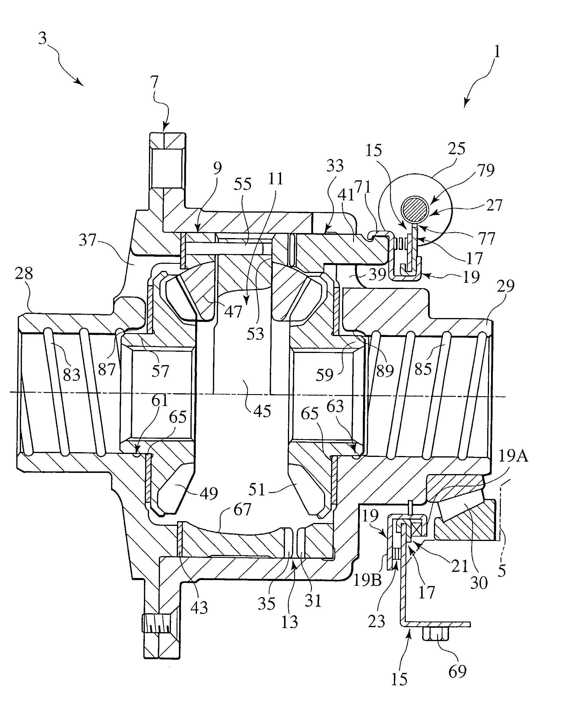
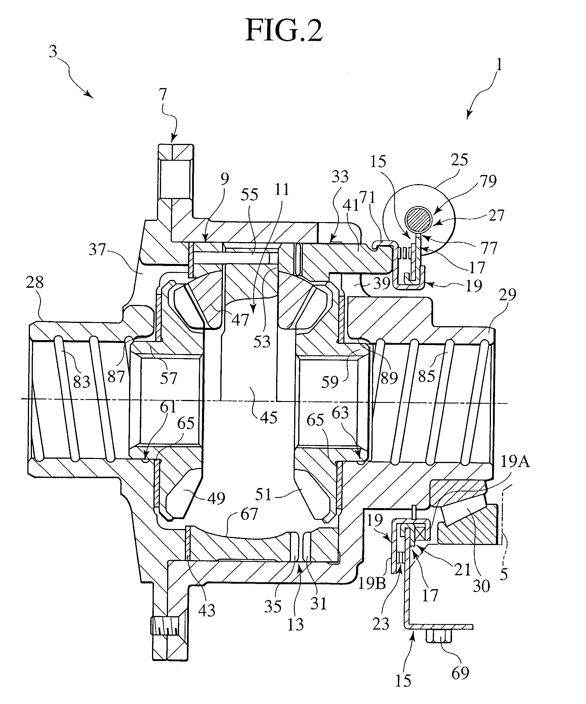
[0099]An actuator 1 of a first embodiment and a front differential 3 (deferential unit) using this actuator are described below with reference to FIGS. 2 and 3.

[0100]FIG. 2 shows a longitudinal cross section of the front differential 3, with its left and right directions corresponding to associated left and right directions of a four-wheel-drive vehicle in which the front differential 3 is employed.

[0101]The front differential 3 is located internally of a differential carrier 5, which is internally formed with an oil sump.

[0102]The front differential 3 is comprised of an actuator 1, an outer differential case 7, an inner differential case 9, a differential mechanism using a bevel gear 11 and a dog clutch 13 (an operative unit).

[0103]Further, the actuator 1 is comprised of a support plate 15 (a stationary member), a cam plate 17 (a rotational member), a thrust plate 19 (a movable member), a cam 21 (a converting mechanism), a shift spring (an urging member), an electric motor 25 (a dr...

second embodiment

[0153][Second Embodiment]

[0154]An actuator 101 of a second embodiment and a front differential 103 (differential unit) using the same are described below with reference to FIG. 4.

[0155]The front differential 103 is replaced with the front differential 3 of the four-wheel-drive vehicle used in the first embodiment. Hereinafter, the same component parts as those of the actuator 1 and the front differential 3 bear the same reference numerals and are referred to for description on different points.

[0156]The front differential 103 is comprised of an actuator 101, the outer differential case 7, the inner differential case 9, the differential mechanism 11 having the bevel gear, and the dog clutch 13.

[0157]Further, the actuator 101 is comprised of a support plate 105 (a stationary member), a screw mechanism 107 (a converting mechanism), a rotational plate 109 (a rotational member: a movable member), an intermediate plate 111 (an operating force transmitting member), a shift spring 113 (an u...

third embodiment

[0181][Third Embodiment]

[0182]An actuator 201 and a front differential 203 (a differential unit) using the same are described below with reference to FIG. 5.

[0183]The actuator 201 is a modified form of the actuator 101 of the second embodiment. Hereinafter, the same component parts as those of the actuator 101 and the front differential 103 bear the same reference numerals and are referred to herein for description of the parts on different points.

[0184]The front differential 203 is comprised of an actuator 201, the outer differential case 7, the inner differential case 9, the differential mechanism 11 having the bevel gear, and the dog clutch 13.

[0185]Further, the actuator 201 is comprised of the support plate 105 (the stationary member), the screw mechanism 107 (the converting mechanism), the rotational plate 109 (the rotational member: the movable member), a magnet plate 205 (an operating force transmitting member), the shift spring 113 (the urging member), the gear set 117 (the ...


PUM


Abstract

An actuator 1 is disclosed including a stationary member 15, a rotational member 17 disposed for rotating capability with respect to the stationary member 15, a movable member 19 disposed for movements with respect to the rotational member 17, a drive power source 25 rotating the rotational member 17, and a converting mechanism disposed between the rotational member 17 and the movable member 19 to convert rotation of the rotational member to an operating force for an operative unit.

Description

BACKGROUND OF THE INVENTION[0001]The present invention relates to actuators that operate operative units such as clutches and, more particularly, to an actuator having a cam converting mechanism or a gear converting mechanism using an electric motor as a drive power source.[0002]FIG. 1 shows a differential unit 2001 disclosed in Japanese Patent Application Publication No. 5-54574. This differential unit 2001 has a drive power connecting and disconnecting mechanism mounted at an input side of a differential mechanism.[0003]The differential unit 2001 is accommodated in a differential carrier 2003. And, the differential unit 2001 is comprised of an outer differential case 2005, an inner differential case 2007, a differential mechanism 2009 having a bevel gear, a meshing clutch 2011 and an actuator 2013 using a fluid pressure.[0004]The meshing clutch 2011 is disposed between a clutch ring 2015 connected to the inner differential case 2007 for free movements and the outer differential ca...

Claims


Application Information

Patent Timeline
IPC IPC(8): H02K7/10H02K7/108F16H48/38F16H48/08F16H48/20F16H48/24F16H48/30F16H48/34
CPCF16H48/24F16H48/34H02K7/108F16H48/08F16H2048/204F16H2048/343F16H48/38F16H48/20
Inventor TERAOKA, MASAOSUDOU, NORIYUKITAKAHASHI, GIICHIROUFUSEGI, MASAAKIAIKAWA, MASASHITOMITA, TETSUSHI
Owner TOCHIGI FUJI IND CO LTD
Learn More