
Low phase noise frequency converter

a frequency converter and low phase noise technology, applied in the field of low phase noise frequency conversion methods and apparatuses, can solve the problems of significant phase noise, error signal, corrupted output rf signal, etc., and achieve the effect of eliminating divider phase noise and high resolution

Inactive Publication Date: 2005-11-22
UNIQUE BROADBAND SYST
View PDF13 Cites 30 Cited by
  • Summary
  • Abstract
  • Description
  • Claims
  • Application Information

AI Technical Summary

Benefits of technology

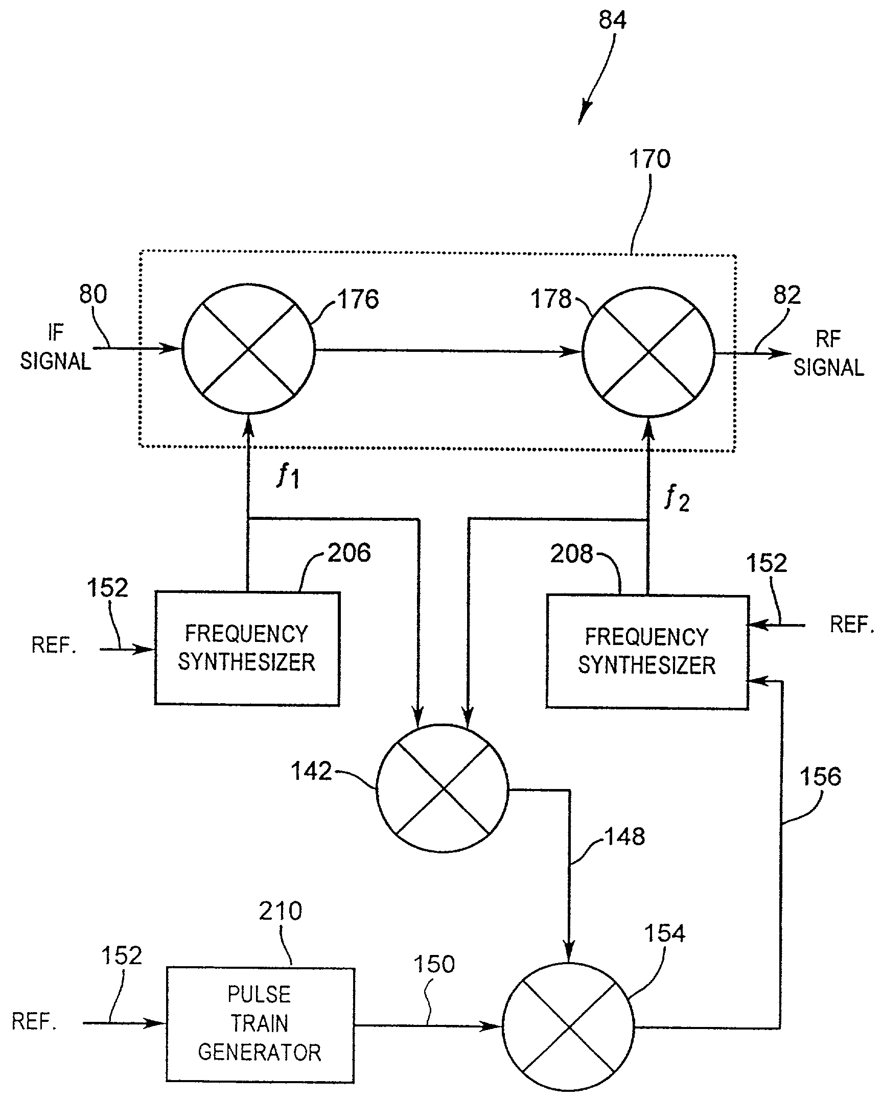
"The present invention is a frequency conversion circuit that uses two local oscillators based on an external reference frequency to perform frequency conversion. This circuit eliminates the issue of divider phase noise and provides high-resolution frequency conversion. It is suitable for receivers and transmitters, especially for multi-carrier modulated systems such as OFDM digital television systems. Additionally, the invention includes a sampling circuit that generates an error signal to adjust the frequency of the second oscillator. The technical effects of this invention include improved frequency conversion and reduced phase noise."

Problems solved by technology

This latter frequency conversion typically results in the introduction of significant phase noise partially attributable to divider noise.
This comparison results in a error signal that can be used by the synthesiser to adjust the oscillator signal.
The operation of dividing the oscillator signal introduces phase noise that becomes amplified and introduced into the oscillator signal and that then corrupts the output RF signal.
A further difficulty is that the resolution of a frequency converter wherein the oscillators are controlled by frequency synthesizers is limited by the step size of the frequency synthesizers.

Method used


Image

  • Low phase noise frequency converter
  • Low phase noise frequency converter
  • Low phase noise frequency converter

Examples


Embodiment Construction

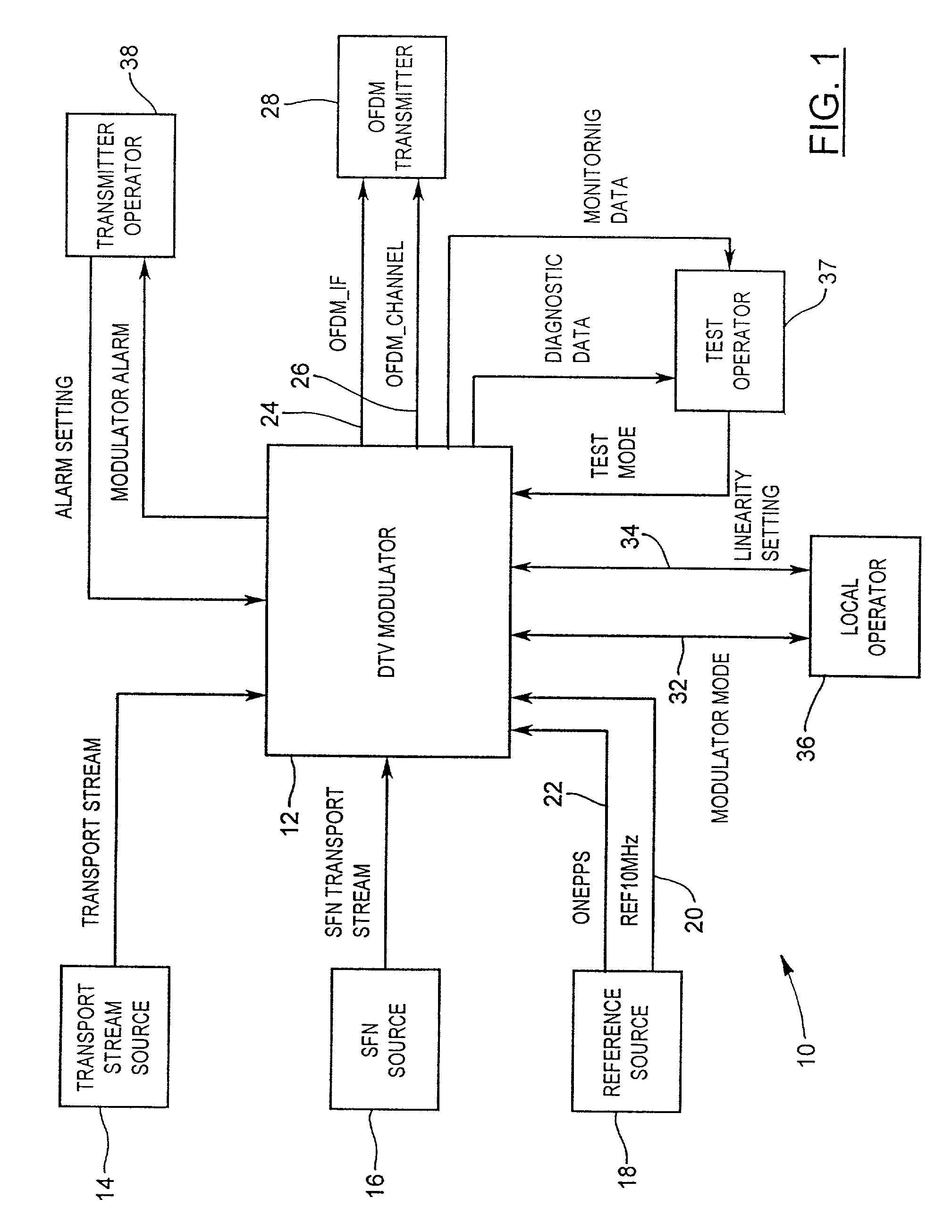
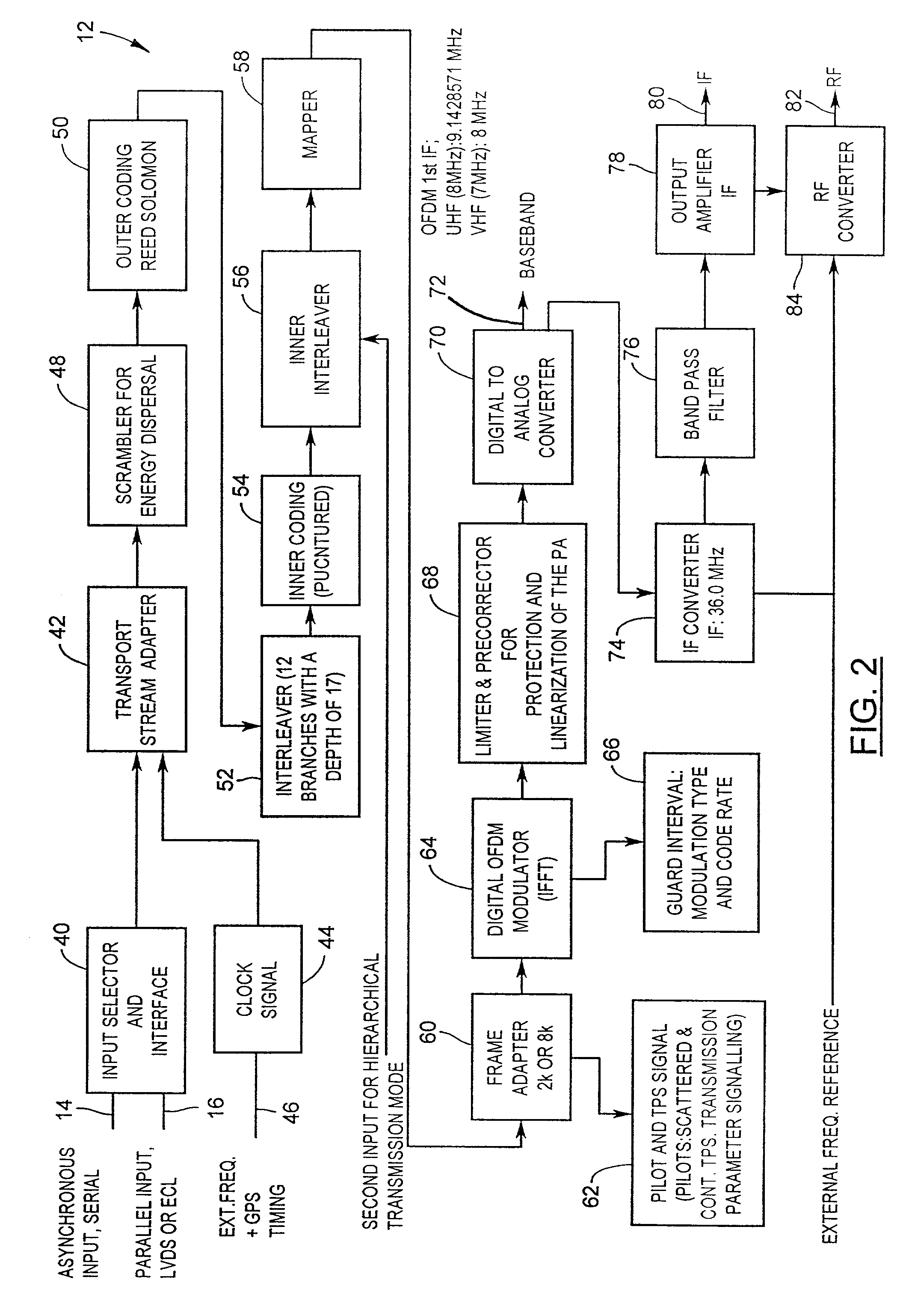
[0019]Referring to the simplified block diagram of FIG. 1, one aspect of the present invention is a digital TV system 10 that, in one embodiment, includes a single board DTV (digital television) modulator 12. DTV modulator 12 receives inputs from at least one source, such as a transport stream source 14 and / or an SFN (Single Frequency Network) source 16. DTV modulator 12 also receives reference inputs from a reference source 18, which includes a 10 MHz reference signal 20 and a 1 PPS reference signal 22. In one embodiment, reference signals 20 and 22 are highly accurate timing signals derived from GPS (Global Positioning System) satellites. These inputs are processed by DTV modulator 12 to produce outputs 24, 26 that are transmitted by OFDM (Orthogonal Frequency Division Multiplex) transmitter 28. Information concerning modulator mode 32 and linearity setting 34 are exchanged with a local operator 36, and various tests, alarms and monitoring data are exchanged with a test operator 3...


PUM


Abstract

One aspect of the present invention is a frequency conversion circuit having a pair of local oscillators. The local oscillators are frequency synthesizers based on an external frequency reference. The frequency conversion circuit is configured to perform a frequency conversion to an input signal equal to a frequency difference of signals from the pair of local oscillators; to generate an oscillator frequency difference signal; to generate an error signal using the oscillator frequency difference signal and an internal reference signal derived from the external frequency reference; and to adjust a phase of one of the pair of oscillators using the error signal. The above-described frequency conversion circuit embodiment essentially eliminates divider phase noise such as that generated by traditional prescalers. In addition, the use of two local oscillators provides a frequency conversion circuit capable of wide-range frequency conversion and high resolution. This frequency conversion circuit embodiment is suitable for receivers as well as transmitters, and is particularly suitable for digital television systems.

Description

[0001]This application claims the benefits of U.S. Provisional Application No. 60 / 216,197 filed Jul. 6, 2000, entitled “Digital television system using coherent orthogonal frequency division coder / modulator” and of U.S. Provisional Application No. 60 / 230,675, filed Sep. 7, 2000, entitled “Low phase noise upconverter / tuner for digital television system,” both of which are hereby incorporated by reference in their entirety.BACKGROUND[0002]This invention relates generally to frequency conversion methods and apparatus, and more specifically to low phase noise frequency conversion methods and apparatus particularly suitable for reception and transmission of digital signals including multi-carrier modulated signals.[0003]The European Broadcasting Union (EBU) European Telecommunications Standards Institute (ETSI) Joint Technical Committee (JTC) has published a draft standard EN300 744 v. 1.2.1 (1999–01) for digital television broadcasting, specifying the framing structure, channel coding, ...

Claims


Application Information

Patent Timeline
Patent Type & Authority Patents(United States)
IPC IPC(8): H03D7/00H03D7/16H03L7/22H03L7/16H04N7/24H04N5/455H04L27/26H04N5/44H03L7/23H04N21/2383H04N21/438
CPCH03D7/163H03L7/22H03L7/23H04N5/455H04N21/2383H04N21/4382H04L27/2626H04N5/4401H04N21/426
Inventor NIELSEN, GERT LYNGE
Owner UNIQUE BROADBAND SYST
Learn More