Use of cutting velocities for real time pore pressure and fracture gradient prediction

a cutting speed and fracture gradient technology, applied in seismology for waterlogging, instruments, borehole/well accessories, etc., can solve the problems of limited use of cuttings, no commercially available tools, and risk of gas kick/blowout, etc., to accurately predict pore pressure and fracture gradient

Inactive Publication Date: 2005-11-22
SHELL OIL CO
View PDF5 Cites 32 Cited by
  • Summary
  • Abstract
  • Description
  • Claims
  • Application Information

AI Technical Summary

Problems solved by technology

While there are no commercially available tools for measurement of pore pressure ahead of the drilling bit, methodologies have been developed to calculate pore pressure in logged intervals using resistivity and / or sonic logs.
A problem often encountered when drilling wells in many parts of the world is narrow drilling margins which require great precision in both pore pressure and fracture gradient prediction in order to prevent any shale instability problem resulting in risk of lost circulation and / or gas kicks / blowouts.
The use of cuttings has been limited in the past partly due to the difficulties in performing measurements on very small samples.

Method used


Image

  • Use of cutting velocities for real time pore pressure and fracture gradient prediction
  • Use of cutting velocities for real time pore pressure and fracture gradient prediction
  • Use of cutting velocities for real time pore pressure and fracture gradient prediction

Examples


example i

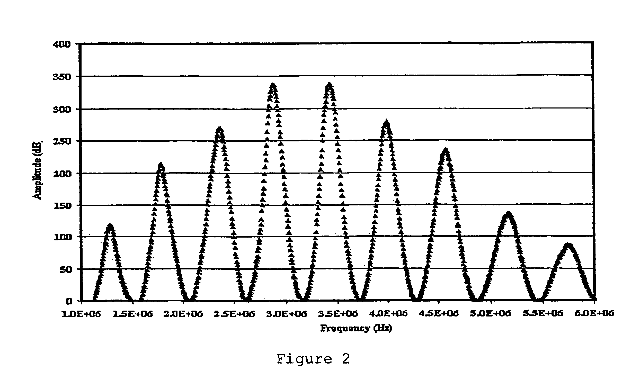
[0097]Reference materials were tested in the laboratory and at the rig site to verify the accuracy of the velocity measurement methodology (CWT) that is the source of the input data for the methodology discussed in this invention. Results of some reference experiments are shown in FIG. 3. The salt sample used in the measurement had an impurity in it. Therefore, two different Δf values were obtained corresponding to the pure halite and impurity, respectively. Resulting CWT velocity versus frequency indicates two different velocities based on the two different Δf values.

example ii

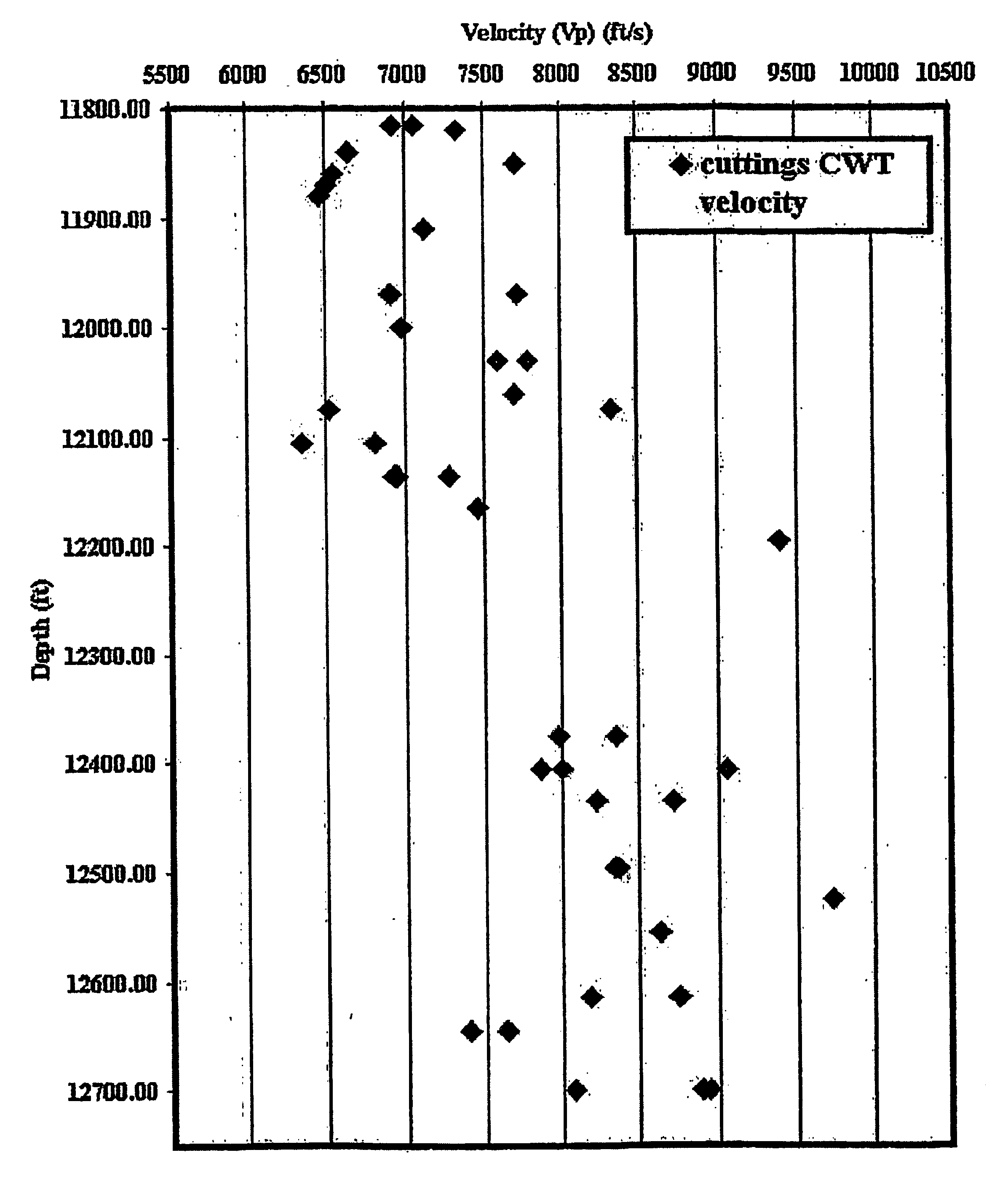
[0098]The tool was field tried at a Gulf of Mexico rig site and real time CWT measurements were conducted at a specific hole interval. During the drilling, sonic LWD was not run due to large hole size. Therefore, CWT velocities provided the only real time source while drilling for calibration of the pore pressure predicted from seismic data before drilling. The recorded velocity versus depth from the selected interval is shown in FIG. 4. Corresponding pore pressure and fracture gradient obtained from the CWT velocities presented in FIG. 4 and from the dielectric coefficient measurements using drill cuttings are shown in FIG. 5. After the interval was drilled, wireline sonic data was collected. A comparison of the wireline velocities and CWT velocities are presented in FIG. 6. The resulting pore pressure and fracture gradient comparison between seismic, wireline sonic, CWT velocities and DCM derived fracture gradient are summarized in FIG. 7. It is evident from FIG. 7 that the CWT an...

example iii

[0099]Cuttings from another Gulf of Mexico well have been used to predict pore pressure and fracture gradient using CWT velocities and DCM measurements. Predicted pore pressure and fracture gradient obtained from the velocities and DCM are presented in FIG. 8 along with log-derived pore pressure and fracture gradient profiles, and the RFT (actual fluid pressure data measured from repeated formation tests) and LOT data (leak off test data conducted at various casing shoe depths at nearby wells in the field) already available. The agreement from CWT predicted pore pressure and RFT data are excellent.


PUM

PropertyMeasurementUnit
lengthaaaaaaaaaa
lengthaaaaaaaaaa
thickaaaaaaaaaa

Abstract

Disclosed is a new method for providing accurate real time predictions of pore pressure and fracture gradient, at the rig site by determining the wave velocity from drill cuttings by a portable continuous wave technology (CWT) tool that measures drill cuttings at high resonant frequency and then using the velocity obtained in combination with the novel method of the present invention to arrive at accurate predictions for pore pressure and fracture gradient. The new technique offers real time pore pressure prediction at the rig site with small error margin that is not otherwise available using seismic, VSP, or check shot velocities in exploration.

Description

[0001]This application claims the benefit of Provisional Application No. 60 / 336,348, filed Oct. 24, 2001.FIELD OF THE INVENTION[0002]This invention generally relates to the analysis and interpretation of acoustic wave velocities in drill cutting samples. More particularly, this invention relates to a new method for providing very accurate real time predictions of pore pressure, fracture gradient, and formation strength at the rig site by determining the velocity of drill cuttings by means of a portable continuous wave technology (Hereafter referred to as CWT) tool that measures drill cuttings at high resonant frequency and using the velocity measurement obtained in combination with the method of the present invention to arrive at accurate predictions for pore pressure and fracture gradient. The new technique offers real time pore pressure prediction at the rig site with small error margin that is not otherwise available using seismic, vertical seismic profiling (VSP), or check shot ...

Claims


Application Information

Patent Timeline
Patent Type & Authority Patents(United States)
IPC IPC(8): E21B49/00G01V1/50G01V1/40
CPCE21B49/005G01V1/50
Inventor TUTUNCU, AZRA NURMYERS, MICHAEL TOLBERTARASTEH, MOHAMMAD MICHAEL
Owner SHELL OIL CO
Why Eureka
Try Eureka