Apparatus and methods for connecting a movable subsystem to a frame

a technology of movable subsystems and frames, applied in the direction of furniture parts, manufacturing tools, instruments, etc., can solve the problems of reducing the number of individual parts needed to assemble a slide assembly, and affecting the assembly speed of the slide assembly. , to achieve the effect of reducing the total number of individual parts necessary to assemble the slide assembly, reducing the number of individual parts, and reducing the number of assembly steps

Inactive Publication Date: 2005-11-29
XEROX CORP
View PDF15 Cites 14 Cited by
  • Summary
  • Abstract
  • Description
  • Claims
  • Application Information

AI Technical Summary

Benefits of technology

[0009]The problem of wear between the locating pins and the machine frame may be addressed by installing bushings or other such elements in the mounting pin holes of a machine frame. Thus, when the bushings are worn due to continuous contact with the locating pins, they may be replaced without having to replace the entire machine frame. Conversely, the locating pins may also be removably mounted on the subsystem, subsystem frame or slide, such that they may also be replaced periodically when they become worn. In addition, sleeves may be provided on the locating pins that may be replaced when sufficiently worn. While the use of bushings, removable locating pins and sleeves may temporarily address the problem, they still require periodic maintenance to ensure that the machine continues to function at an optimum level.
[0012]In various exemplary embodiments of this invention the biasing force applied by each urging member may be equivalent to the gravity induced load the subsystem exerts on the portion of the slide where the urging member is located. For example, one quarter of the mass of the subsystem. However, any number of urging members may be used, thereby varying the necessary biasing force to be applied by each urging member. In addition, the biasing force of each urging member may be varied based on the total percentage of the weight of the subsystem to be countered by all of the urging members. Because the urging member is exerting a force upward as the subsystem closes, it tends to counter the weight of the subsystem. This causes the pin to hole force to be minimized thereby reducing the wear on the locating pins and corresponding holes, as well as the frictional force required to insert the locating pins into their corresponding holes in the machine frame.
[0014]In various exemplary embodiments of this invention, minor side-to-side motion of the subsystem may be allowed by compliance of the slide. In other exemplary embodiments, additional side-to-side motion may be allowed for, by installing a plate on the machine frame that is free to slide in one or more directions on the machine frame itself. The slide is then mounted to the plate, thus relieving any horizontal forces that may be transmitted from the machine frame to the slide. In one exemplary embodiment of this invention one side of the subsystem has mounting pins and projections that mount directly in openings in the machine frame, thus, having very little horizontal float. The other slide incorporates a plate that rests on the cut edge of tabs bent out of the back of the machine frame. The projection or tongue is inserted through an opening in the plate.
[0015]In this embodiment, the slide has little horizontal float in the plate, but the plate is free to move side-to-side relative to the machine frame. The corresponding pins on this side of the subsystem fit into holes in the machine frame that are elongated in a horizontal direction, for example, allowing the pins to float horizontally in the machine frame. This feature fixes the slide in a vertical direction. In this way, the load capacity of the slide is not compromised by letting the axis of maximum section modulus move off of vertical. In addition, this feature reduces lateral forces on the slides and subsystem, thus preventing warping that may occur to the slides or the subsystems.
[0019]In various exemplary embodiments of this invention, a slide assembly, which may encompass one or more slides, may be interchangeably mounted on a machine frame or plate. In other words, the entire slide assembly may be flipped upside down and mounted in the machine frame. In addition, because each individual slide may be interchangeable, the total number of individual parts necessary to assemble a slide assembly may be reduced.
[0020]The systems and methods of this invention also allow for greater speed in the mounting of a subsystem in a machine. In one exemplary embodiment of this invention the urging member or spring may be easily twisted and snapped onto the tab on the backplate or machine frame. The slide may then be simply pushed through an opening in the machine frame or plate without further adjustments. Thus, no screws or other fasteners are necessary and important assembly sequences are also not required.

Problems solved by technology

These locating pins or other such devices, may tend to resist the motion of the slides when a subsystem is being docked or undocked, due to a lack of compliance and misalignment due to tolerance between the locating pins and their corresponding holes in the machine frame.
In other words, the locating pins or other devices may contact i.e., rub against, for example, the surface(s) of the machine frame defining their corresponding holes, which after continuous or extended usage, may result in damage to the locating pins and / or machine frame, and / or may make it more difficult for an operator to slide the subassembly.
However, this is not a very fast assembly procedure and may be easily skipped or done incorrectly.
However, the slide mount screws may ultimately become loose again, thereby requiring periodic maintenance.
This lack of alignment may ultimately be manifested, for example, by the locating pins dropping due to the deformation / warping of the slide.
The slides may become deformed / warped due to being subjected to the weight of the subsystem over time.
However, the lack of alignment between the locating pins and their corresponding holes may be caused by other reasons.
For example, other acting forces of various components of the apparatus may cause a lack of alignment such as gravity acting to distort the frame if supported on rough or uneven surfaces.
The above circumstances may eventually result in high loads being exerted on the surfaces of the machine frame that defines the holes by the location pins.
These loads will increase the force necessary to open and close the subsystem and also increase wear on various features of the machine, such as the surfaces of the machine frame defining the holes.
In particular, a large amount of wear and deformation may be experienced on the locating pins and the corresponding holes in the machine frame.
This wear may reduce mounting precision and thereby be responsible for mislocation of the subsystem relative to the machine frame and other components, which in turn can create operational problems with the machine, such as producing paper jams and creating bad images in the case of an imaging device, for example.
A lack of mounting precision can also cause other non-operational problems.

Method used


Image

  • Apparatus and methods for connecting a movable subsystem to a frame
  • Apparatus and methods for connecting a movable subsystem to a frame
  • Apparatus and methods for connecting a movable subsystem to a frame

Examples


Embodiment Construction

[0032]For convenience of explanation, exemplary embodiments of the invention are described below with reference to the figures in the context of an imaging device, such as a copier, fax machine printer or the like. However, as previously discussed, all exemplary embodiments of the invention are intended to be used in any applicable field of endeavor.

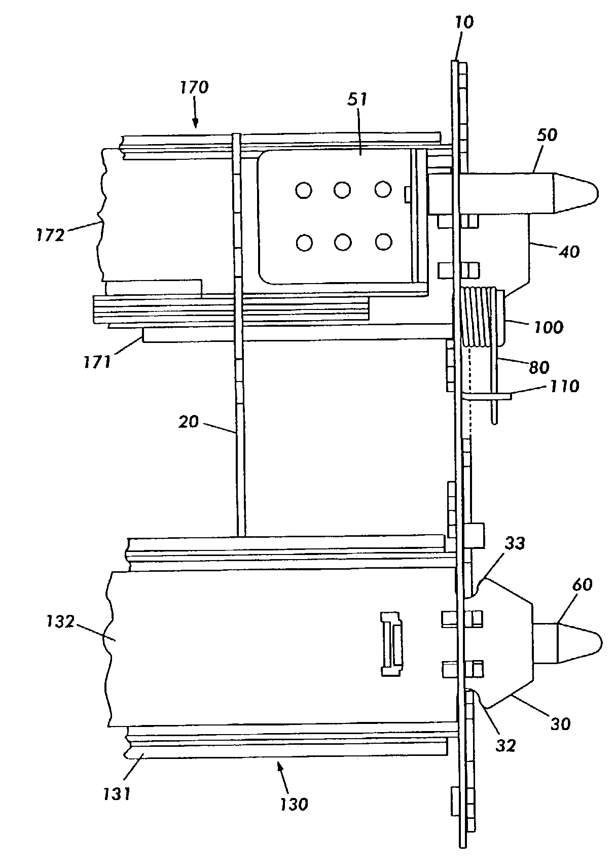
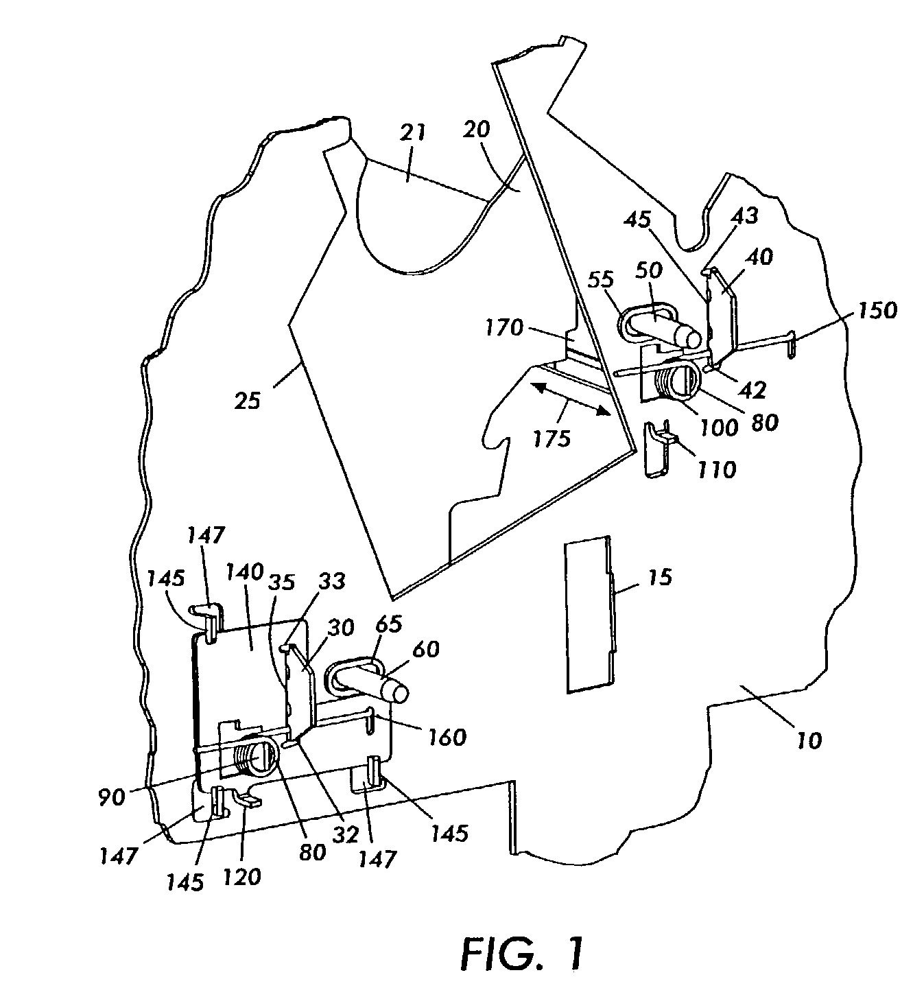
[0033]FIG. 1 shows an exemplary embodiment of a subsystem slide retainer that is mounted to a machine frame 10. The machine frame 10 could be located in a device such as a fax machine, printer or copier, for example. Further, the machine frame 10 could be any type of member that is capable of supporting at least a portion of the weight of the subsystem 21 and subsystem frame 20. As illustrated in FIG. 1, the machine frame 10 is illustrated from its back side, having most of the accessible portions of the machine located on its opposite side. In various exemplary embodiments of this invention the back side of the machine frame 10 may not ...


PUM

PropertyMeasurementUnit
massaaaaaaaaaa
angleaaaaaaaaaa
weightaaaaaaaaaa

Abstract

An assembly has a frame that defines at least one opening and a subsystem that is movable relative to the frame. At least one slide connects the subsystem to the frame such that the weight of the subsystem transmits a force to the slide. The slide includes at least one projection that extends through the at least one opening in the frame. At least one urging member biases the projection to at least partially counter the force transmitted to the slide by the weight of the subsystem. At least one docketing pin slides into at least one docking hole with minimal vertical load on the docking hole.

Description

BACKGROUND OF THE INVENTION[0001]1. Field of Invention[0002]This invention relates to apparatus and methods for connecting a movable subsystem to a frame.[0003]2. Description of Related Art[0004]Many machines, such as imaging devices, copiers, fax machines and printers, for example, have subsystems that are movable relative to other components of the machine, such as a machine frame, for example. These subsystems may be moved for various reasons, for example, routine maintenance or to replace a dispensable material, such as paper, ink or toner, for example. In one example, the front panel of a copier may be opened and a subsystem, such as a fuser or paper drawer, may be slid out for maintenance or for reloading. These and other subsystems may be mounted on various types of sliding devices to allow them to be removed and replaced with an adequate amount of precision.SUMMARY OF THE INVENTION[0005]Machines that have slidable subsystems, i.e., subsystems that are slidable relative to ot...

Claims


Application Information

Patent Timeline
Patent Type & Authority Patents(United States)
IPC IPC(8): A47B88/00B21D53/10B23P11/00B41J29/02G03G21/16
CPCB41J29/02G03G21/1619G03G21/1633G03G2221/1684Y10T29/49904Y10T29/4984Y10T29/49696
Inventor FROMM, PAUL M.BENTON, RICHARD C.
Owner XEROX CORP
Why Eureka
Try Eureka