Method of manufacturing nozzle plate

a technology of nozzle plate and nozzle orifice, which is applied in the direction of metal-working equipment, printing, writing implements, etc., can solve the problems of low precision, low jet stability, and inability to accurately measure the size and shape of the nozzle orifice, so as to achieve simplified regulation

Inactive Publication Date: 2005-11-29
SEIKO EPSON CORP
View PDF13 Cites 10 Cited by
  • Summary
  • Abstract
  • Description
  • Claims
  • Application Information

AI Technical Summary

Benefits of technology

[0052]Accordingly, the nozzle orifices belonging to the same nozzle array have the nozzle profile by the same punch. Therefore, i

Problems solved by technology

In the related manufacturing method, however, it is hard to set the dimensions and shapes of the nozzle orifices to be equal to each other with high precision.
For example, when the length of the straight portion is too great, a jet efficiency is dete

Method used


Image

  • Method of manufacturing nozzle plate
  • Method of manufacturing nozzle plate
  • Method of manufacturing nozzle plate

Examples


first embodiment

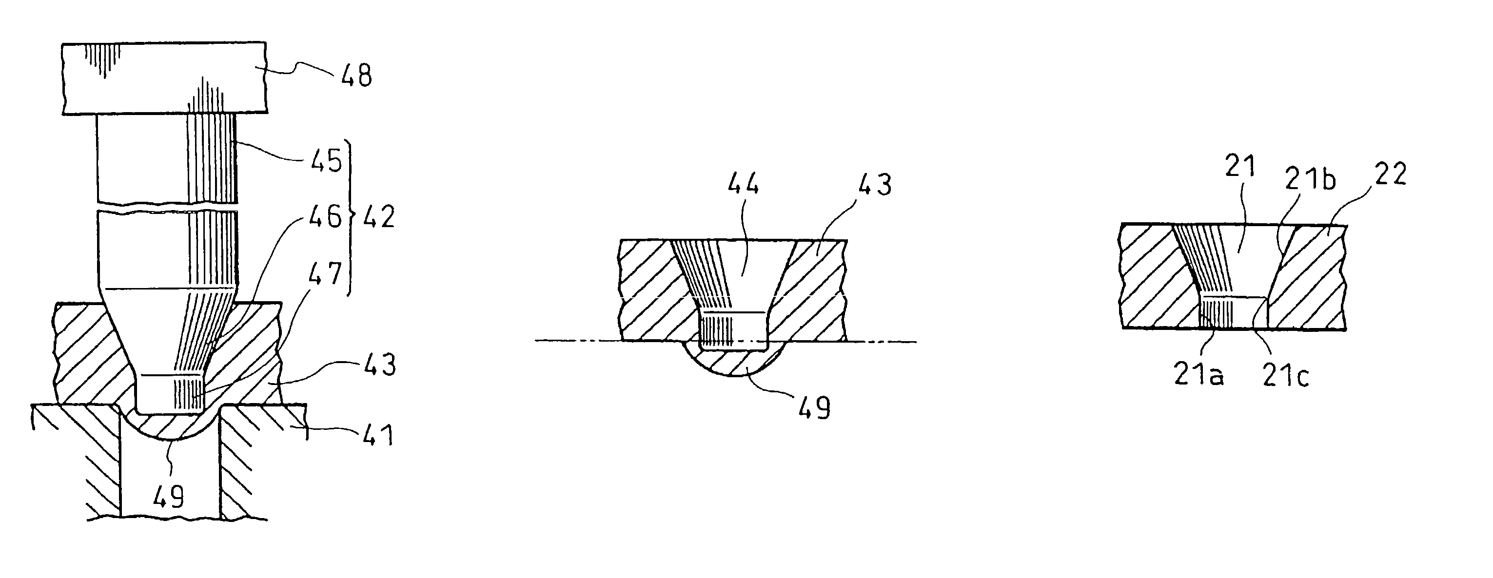
[0075]The first embodiment has a feature that the same punch 42 is used to form a plurality of provisional holes 44 belonging to the same nozzle array 30. In the embodiment, various methods can be proposed for the formation of the provisional holes 44. For example, it is possible to propose a method of forming the provisional hole 44 from the first nozzle array 30A to the eighth nozzle array 30H in order by one punch 42. Moreover, it is also possible to employ a method of forming the provisional holes 44 in the nozzle arrays 30A to 30H by eight punches 42 in total by causing one punch 42 to correspond to one nozzle array 30, that is, a method of arranging a plurality of punches 42 which are independently movable in the direction of the nozzle arrays 30, thereby forming the provisional hole 44 in each nozzle array 30 by each punch 42. In any method, the punch 42 is moved along a virtual center line 51 set to the formation position of the nozzle array 30, thereby carrying out the punc...

third embodiment

[0094]As shown in FIG. 5, in the third embodiment, nozzle arrays 30 (30A to 30G) are formed transversely at an interval L3. In a punch set 52 (52D to 52G) to be used in this example, an interval between adjacent punches 42 is set to be integer times as much as a formation interval L3 between the nozzle arrays 30. In this example, punching for the nozzle arrays 30 is ended and the punch set 52 is then moved in the direction of the nozzle arrays 30 by a distance defined by the formation interval L3 between the nozzle arrays 30, thereby carrying out the punching for the next nozzle array 30.

[0095]For example, a fourth punch set 52D includes two punches 42 and an attachment interval between the punches 42 is made equal to the formation interval L3 between the nozzle arrays 30. In the punching using the fourth punch set 52D, the processing is carried out for two adjacent nozzle arrays 30 at the same time. For example, the punching is carried out for the first nozzle array 30A and the sec...


PUM


Abstract

A nozzle plate is manufactured by providing a material plate and a punch. The material plate is punched by the punch to form a provisional nozzle orifice hole on the material plate. The punching is repeated such that the provisional holes formed by a given punch are arranged in line. A bulged portion which is bulged on a back side of the material plate is removed to form the completed nozzle orifice.

Description

BACKGROUND OF THE INVENTION[0001]The present invention relates to a liquid jetting head such as a recording head for an ink jet type recording apparatus, a coloring material jetting head for a display manufacturing apparatus, an electrode material jetting head for an electrode forming apparatus or an organism jetting head for a biochip manufacturing apparatus, and a nozzle plate provided in the liquid jetting head and a method of manufacturing the nozzle plate.[0002]A liquid jetting head can jet a liquid in a droplet state and typically includes a recording head used in an image recording apparatus such as an ink jet type printer or an ink jet type plotter and serving to jet a liquid ink. In addition, examples of the liquid jetting head include a coloring material jetting head used in a display manufacturing apparatus for manufacturing a color filter such as a liquid crystal display and serving to jet a liquid coloring material such as R (Red), G (Green) or B (Blue), an electrode ma...

Claims


Application Information

Patent Timeline
IPC IPC(8): B41J2/14B41J2/16B41J2/135
CPCB41J2/1433B41J2/162B41J2/1623B41J2/1626B41J2/1632B41J2/1637Y10T29/49812Y10T29/49798Y10T29/49833Y10T29/49789Y10T29/49813Y10T29/49401B41J2002/14475
Inventor NAKAMURA, TAKASHITAKASHIMA, NAGAMITSUFURUTA, TATSUO
Owner SEIKO EPSON CORP
Why Eureka
Try Eureka