Drag and/or dip finishing machine for the surface machining of workpieces by means of grinding and/or polishing granules in the presence of a liquid machining agent

a technology of surface machining and dip finishing machine, which is applied in the direction of polishing machine, grinding machine, metal-working apparatus, etc., can solve the problems of deficient surface machining, high cost, and sticky deposits on workpieces, and achieves simple and cost-effective design, simple and convenient

Active Publication Date: 2018-08-07
OTEC PRAZISIONSFINISH
View PDF18 Cites 1 Cited by
  • Summary
  • Abstract
  • Description
  • Claims
  • Application Information

AI Technical Summary

Benefits of technology

[0018]According to an embodiment of simple and cost-effective design, it is provided that the liquid discharge unit comprises a suction lance, which is connected to a pump and projects into the chamber. This enables the liquid machining agent to be discharged from the chamber—which is co-rotated with the container or else is stationary or immobile—in a simple and convenient manner, in that the suction lance projects into the container from above.
[0019]The suction lance can preferably be arranged adjustable in height in order to regulate the desired fill height of the machining agent in the container, which fill height corresponds with the fill height of the machining agent in the chamber. This also opens up the possibility of simple regulation of the, in particular optionally adjustable, fill height of the liquid machining agent in the container, so that the fill height can be kept, for instance, at a presettable, constant level, or the fill height level can be changed even during the surface machining. Such regulation of the fill height level can be effected, for instance, such that the suction lance is disposed at a height level in the chamber which corresponds to that fill height of the machining agent in the chamber which corresponds with the desired fill height of the machining agent in the container. Hence the liquid machining agent above the height level of the suction lance is discharged from the chamber, while it remains in place beneath the suction lance in the chamber or in the container fluidically connected thereto. The fill height level of the liquid machining agent in the container can thus be kept constant in accordance with the adjustable height of the suction lance, while fresh machining agent can nevertheless be added to the container, since a corresponding share of “used” machining agent is constantly removed from the container via its chamber.

Problems solved by technology

A problem with the vibratory grinding or polishing machining can consist in the fact that, particularly in the case of the frequently applied wet machining in the presence of a liquid machining agent, during the abrasive contact of the workpieces with the grinding or polishing granules an increasing contamination of the machining agent takes place, which not only calls for a more or less frequent exchange of the machining agent, but can also result in a sticky deposit on the workpieces, so that these must subsequently be cleaned or there is even the risk of deficient surface machining.
The contamination can stem, on the one hand, directly from the grinding stock to be machined, but also from the grinding or polishing granules themselves, which, with increasing residence time, are subjected to a progressive, fine-particle abrasion.
In order to counter this, various additives, such as, for instance, commercially available surfactants, are widely added to the machining agent, yet it has been shown that surfactants are only very limitedly capable of reducing said deposits.
While it is the case that the liquid machining agent can be added without difficulty to the rotationally driven drag or dip finishing machine of the generic type, whether manually or automatically by means of control valves, an evacuation of the liquid machining agent from the container proves complicated and normally requires an interruption of the running of the machine.
However, such a construction proves complicated in design if the container is to be rotated by means of a suitable drive, while, on the other hand, a control or regulation of the respectively desired quantity of liquid machining agent in the container is barely possible.

Method used


Image

  • Drag and/or dip finishing machine for the surface machining of workpieces by means of grinding and/or polishing granules in the presence of a liquid machining agent
  • Drag and/or dip finishing machine for the surface machining of workpieces by means of grinding and/or polishing granules in the presence of a liquid machining agent
  • Drag and/or dip finishing machine for the surface machining of workpieces by means of grinding and/or polishing granules in the presence of a liquid machining agent

Examples


Embodiment Construction

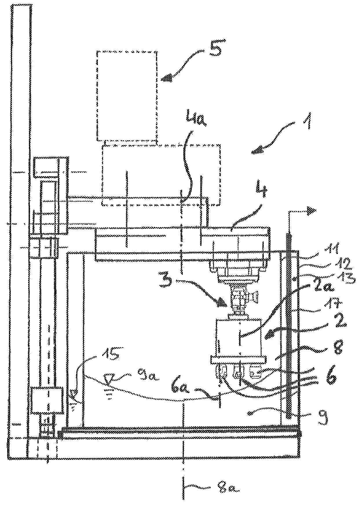
[0035]In FIG. 1, an embodiment of an inventive drag finishing machine 1 for the surface machining of workpieces is represented. The drag finishing machine 1 is equipped with a workpiece holder 2, which is releasably fixed by means of a clamping connection 3 to a movable—here: rotatable—carrying part 4 of the drag finishing machine 1, the so-called plate or rotor. The workpiece holder 2 is here clamped to the carrying part 4 eccentrically in relation to the rotational axis 4a thereof, so that it describes a path curve upon the rotation of the carrying part 4. For its part, the workpiece holder 2 can be fixed on the carrying part 4 rotatably about an axis 2a, such as its longitudinal axis, which can be realized, for instance, by means of a planetary gearing which is disposed in the carrying part 4 and which, upon a rotation of the carrying part 4 about its rotational axis 4a, induces a rotation of the workpiece holder 2 about its rotational axis 2a. The equivalent applies to any furth...


PUM


Abstract

A drag and/or dip finishing machine has at least one workpiece holder for the releasable fastening of the workpieces to be machined and a container, disposed beneath the workpiece holder, for accommodating the grinding and/or polishing granules, wherein the workpiece holder and the container are movable relative to each other in that at least the container is rotationally driven. The container has a chamber, which extends around the whole of the periphery thereof and is fluidically connected to the inside, accommodating the grinding and/or polishing granules, of the container, at least on a lower portion thereof, the chamber being equipped with a liquid discharge unit in order to be able to discharge the machining agent from the chamber in the event of an excess of machining agent in the container.

Description

BACKGROUND OF THE INVENTION[0001]The invention relates to a drag and / or dip finishing machine for the surface machining of workpieces, by means of grinding and / or polishing granules, by movement of the workpieces in a bed of the grinding and / or polishing granules relative to said bed with the addition of a liquid machining agent, comprising at least one workpiece holder for the releasable fastening of the workpieces to be machined and comprising a container, disposed beneath the workpiece holder, for accommodating the grinding and / or polishing granules, wherein the workpiece holder and the container are movable relative to each other in that at least the container is rotationally driven.[0002]The working method of drag and / or dip finishing machines of this type is based on dipping the workpiece to be machined into a bed of the grinding and / or polishing granules located in a container and on moving the workpiece relative to the granules, whereby the surface of the workpiece is ground...

Claims


Application Information

Patent Timeline
Patent Type & Authority Patents(United States)
IPC IPC(8): B24B31/00B24B31/12B24B55/12
CPCB24B31/003B24B55/12B24B31/12
Inventor GEGENHEIMER, HELMUT
Owner OTEC PRAZISIONSFINISH
Why Eureka
Try Eureka