Method of punching small hole and method of manufacturing liquid ejection head using the same

Active Publication Date: 2005-11-29
SEIKO EPSON CORP
View PDF9 Cites 9 Cited by
  • Summary
  • Abstract
  • Description
  • Claims
  • Application Information

AI Technical Summary

Benefits of technology

[0031]Preferably, the through hole is formed at a portion of the metal board which has been subjected to a plastic working.
[0032]Although workability is deteriorated at the portion which has been subjected to the plastic working, an advantage of the invention of stabilizing the metal board, making the damaged punch difficult to be brought about and capable of prolonging the lifetime of the die is remarkable and effective.
[0033]Preferably, the punching method further comprises a step of

Problems solved by technology

Therefore, enhancement of productivity is difficult to achieve to bring about a factor of increasing fabrication cost.
Therefore, there has been tried to form the pressure generating chamber at the board made of the metal by plastic working, however, the working is difficult since the pressure generating chamber is extremely small and the flow path width o

Method used


Image

  • Method of punching small hole and method of manufacturing liquid ejection head using the same
  • Method of punching small hole and method of manufacturing liquid ejection head using the same
  • Method of punching small hole and method of manufacturing liquid ejection head using the same

Examples


Embodiment Construction

[0081]Embodiments of the invention will be explained below in reference to the accompanying drawings.

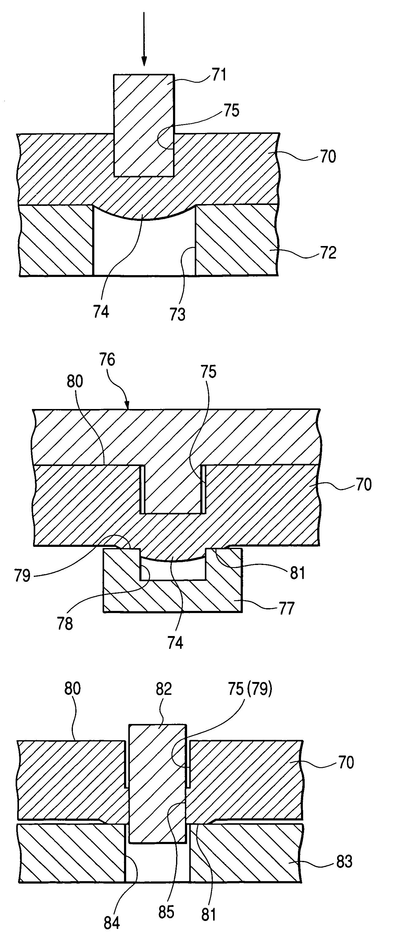
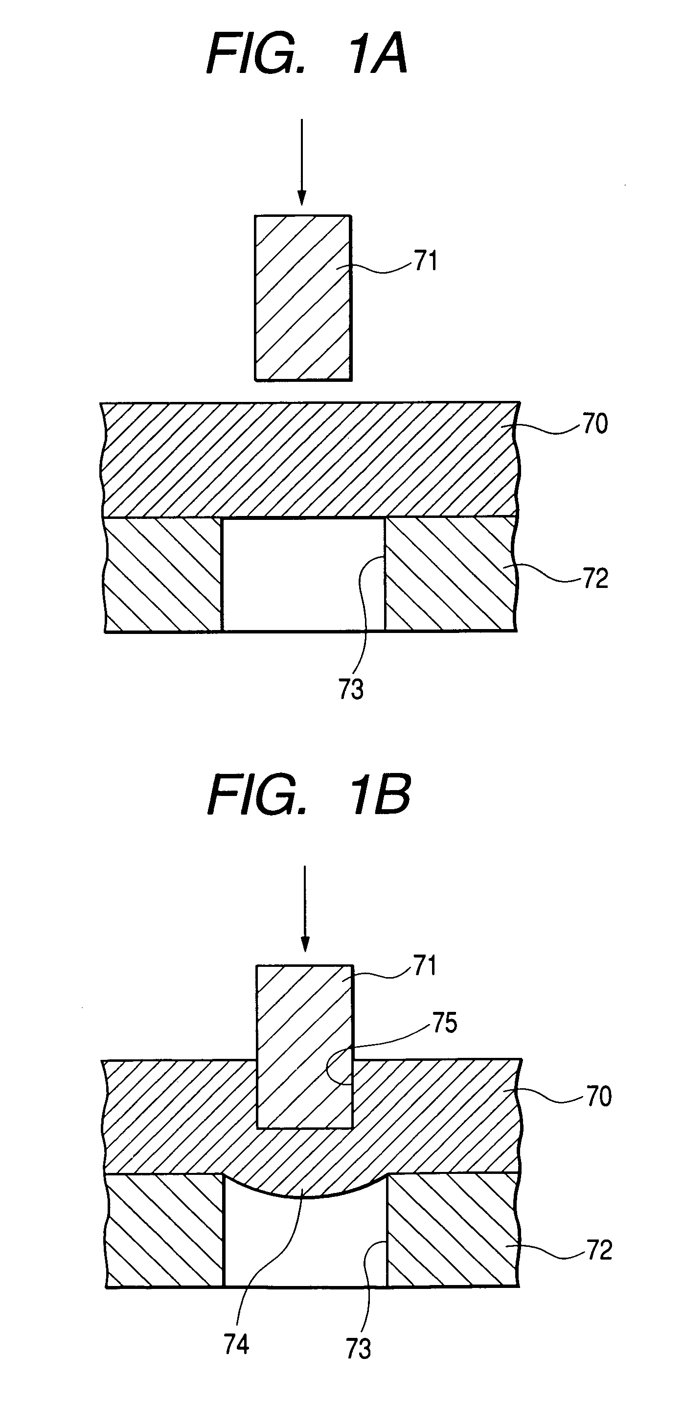
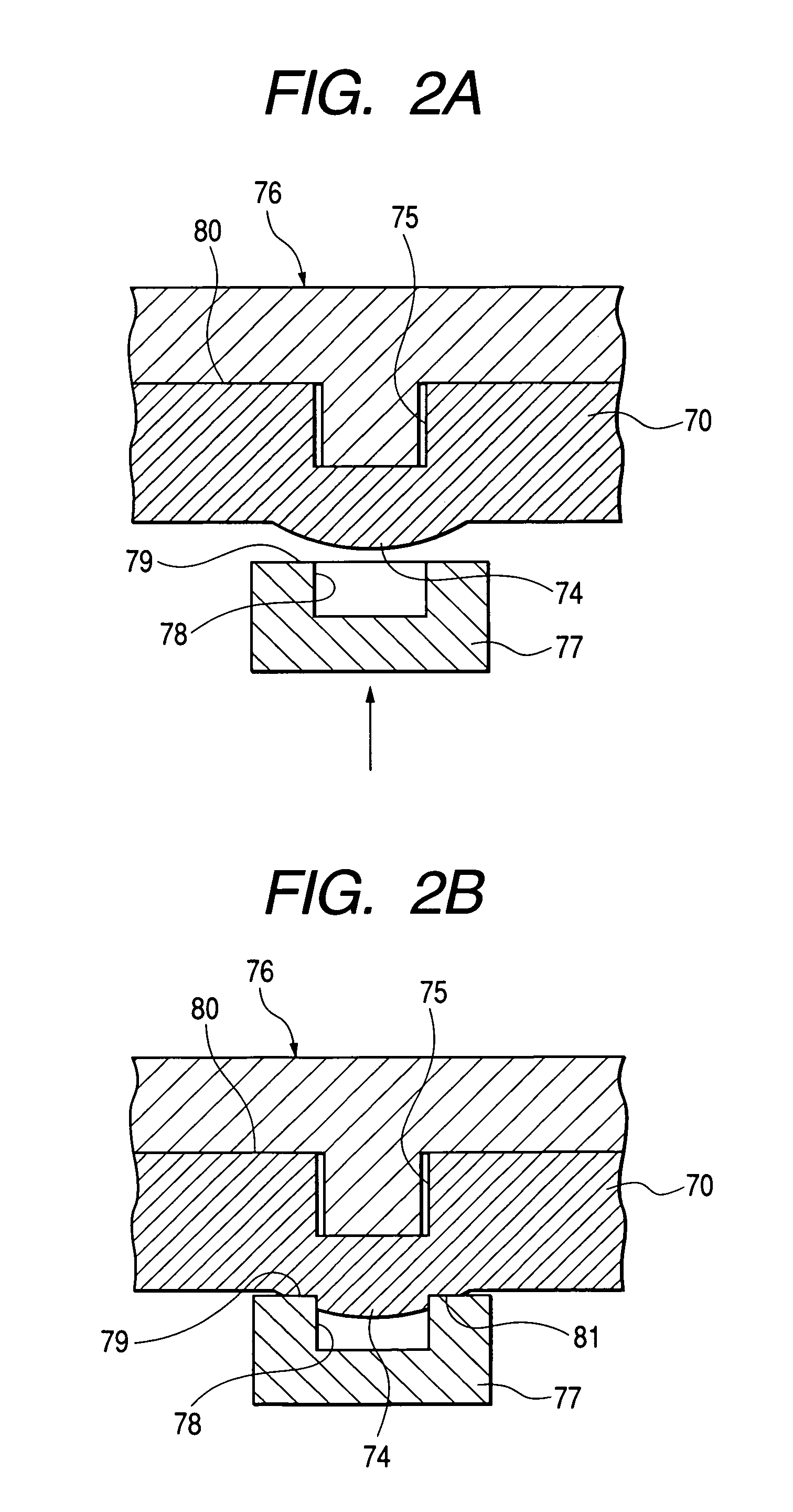
[0082]According to a method of punching a small hole of the invention, a small hole is punched at a metal board 70 by using an upper die and a lower die. In the following explanation, a punch is used as an upper die, a die is used as a lower die, and an explanation will be given by defining an upper die and a lower die used in the first step respectively as a first punch 71 and a first die 72, an upper die and a lower die used in the second step respectively as a second punch 76 and a second die 77, and an upper die and a lower die used in the third step respectively as a third punch 82 and a third die 83.

[0083]According to the method of punching the small hole, first, at the first step, an unpenetrating hole 75 is formed at the metal board 70 by the first punch 71 (FIGS. 1A and 1B). Successively, at the second step, a flat portion 81 is formed on a protrusion 74 formed at a portion ...


PUM

PropertyMeasurementUnit
Lengthaaaaaaaaaa
Widthaaaaaaaaaa
Lengthaaaaaaaaaa

Abstract

An upper die and a lower die are provided. An unpenetrating hole is formed at an upper face of a metal board with the upper die, so that a protrusion is formed on a lower face of the metal board at a portion corresponding to the unpenetrating hole. A flat portion is formed on the protrusion with the lower die. The unpenetrating hole is punched with the upper die while supporting the flat portion with the lower die to form the through hole.

Description

BACKGROUND OF THE INVENTION[0001]The present invention relates to a method of punching a circular or rectangular small hole having a diameter or a long side of not greater than about 0.5 mm at a metal board by using an upper die and a lower die. The present invention also relates to a method of manufacturing a liquid ejection head using such a punching method.[0002]An ink jet recording head (hereinafter, referred to as “recording head”) used as an example of a liquid ejection head is provided with a plurality of series of flow paths reaching nozzle orifices from a common ink reservoir via pressure generating chambers in correspondence with the orifices. Further, the respective pressure generating chambers need to form by a fine pitch in correspondence with a recording density to meet a request of downsizing. Therefore, a wall thickness of a partition wall for partitioning contiguous ones of the pressure generating chambers is extremely thinned. Further, an ink supply port for commun...

Claims


Application Information

Patent Timeline
IPC IPC(8): B21D28/24B21D28/26B41J2/16
CPCB21D28/24B21D28/26B41J2/1623B41J2/1632B41J2/1637B41J2/1612B41J2002/14419Y10T29/49432
Inventor AKAHANE, FUJIOTAKASHIMA, NAGAMITSUHAKEDA, KAZUSHIGEUESUGI, RYOJI
Owner SEIKO EPSON CORP
Why Eureka
Try Eureka