Calibration method and device for long range guided wave inspection of piping

a guided wave and calibration method technology, applied in the direction of instruments, structural/machine measurement, and analysis of solids using sonic/ultrasonic/infrasonic waves, can solve the problems of not being practicable in most occasions, not being able to calibrate the scale by using a reference pipe, etc., and achieve the effect of determining the amount of attenuation per linear distan

Active Publication Date: 2005-11-29
SOUTHWEST RES INST
View PDF5 Cites 53 Cited by
  • Summary
  • Abstract
  • Description
  • Claims
  • Application Information

AI Technical Summary

Benefits of technology

[0025]To determine the amount of attenuation, two clamps may be attached to the pipe a known distance apart. By knowing the distance between the clamps, the amount of attenuation per linear distance can be determined. By knowing the amount of attenuation over a linear dis...

Problems solved by technology

That is not possible most of the time.
Calibration of the scale by using a reference pipe has been found to be impractical in most occasions.
While this approach provides for fairly go...

Method used


Image

  • Calibration method and device for long range guided wave inspection of piping
  • Calibration method and device for long range guided wave inspection of piping
  • Calibration method and device for long range guided wave inspection of piping

Examples


Embodiment Construction

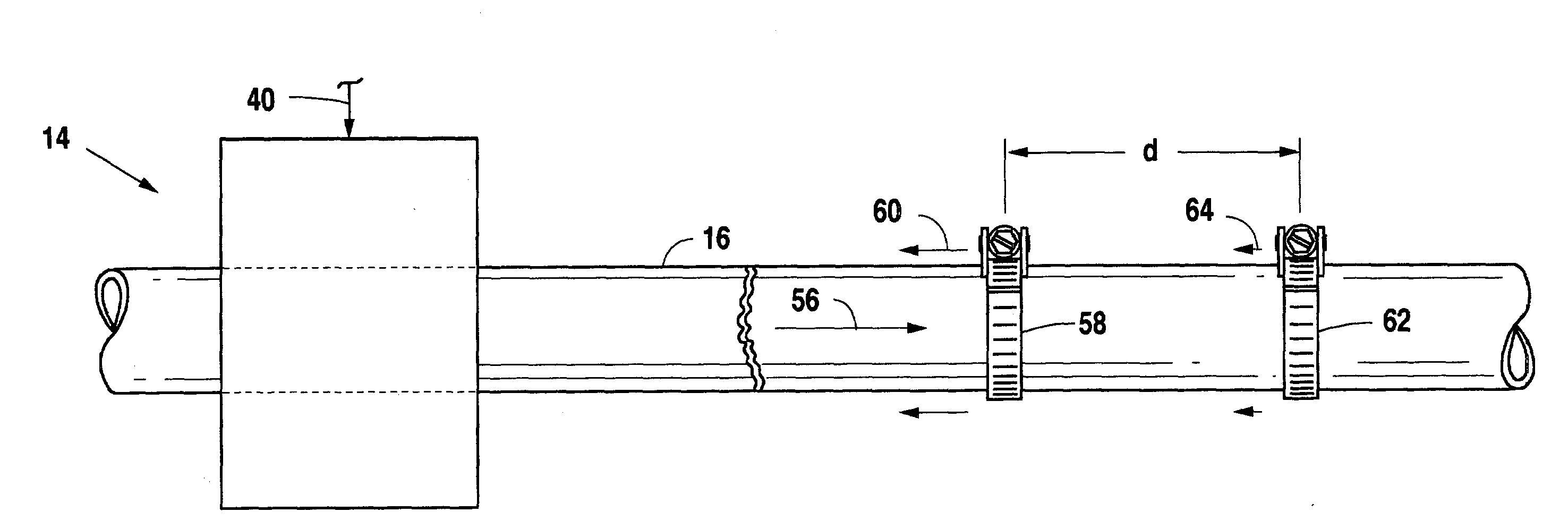
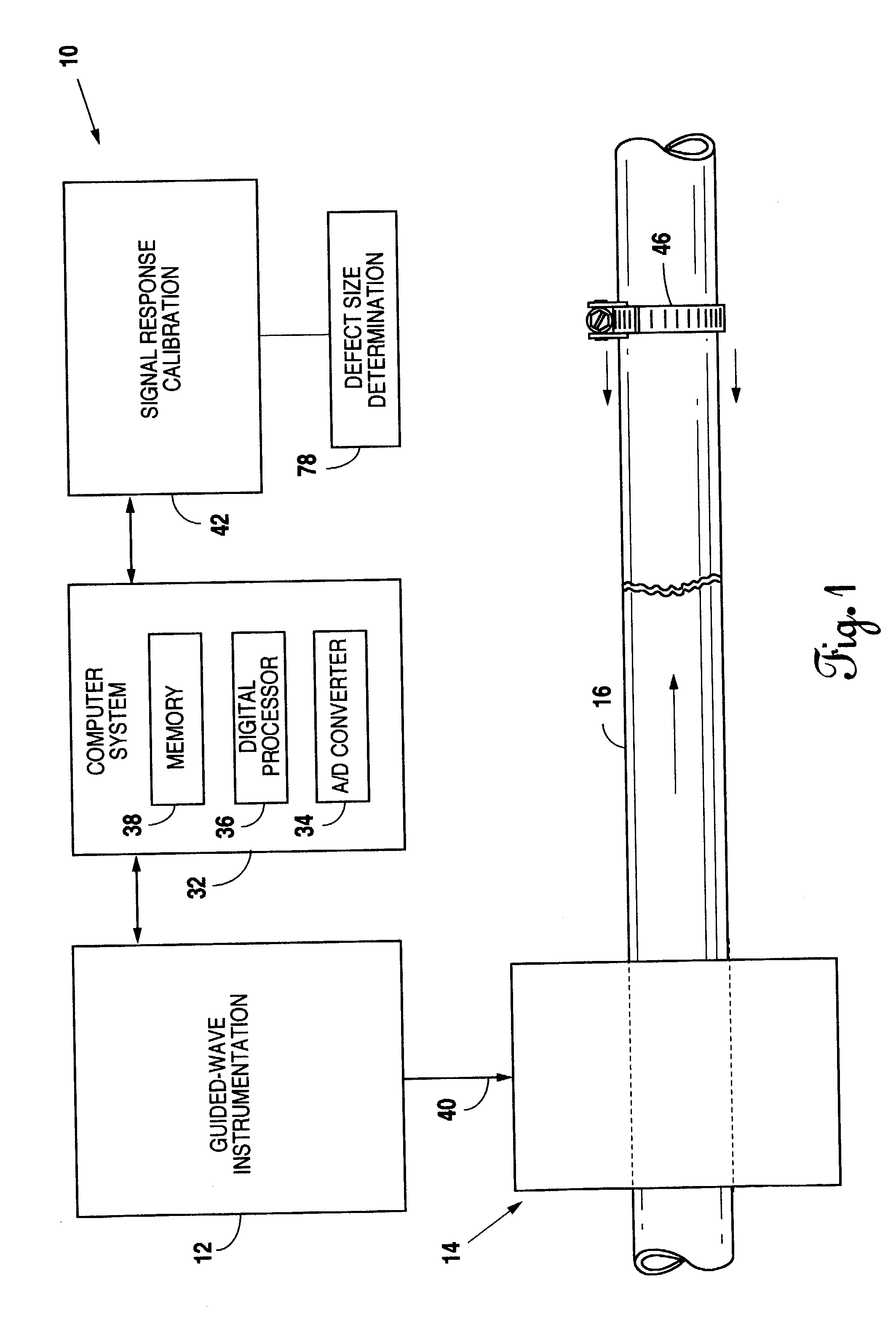
[0032]The present invention is directed towards a simple, reliable, inexpensive method of direct calibration in the field of the scale of a reflected guided wave using guided wave techniques. The scale then can be used to determine the percentage defect represented by any unknown reflected signal. Reference is made to FIG. 1 for description of a complete system that could be used with the present invention. In FIG. 1, an inspection system 10 is shown that includes a guided-wave instrumentation 12 with associated transmitter / receiver probe 14. The transmitter / receiver probe 14 encircles a pipe 16 under test.

[0033]The guided-wave instrumentation 12 generates the appropriate signal for delivery to the transmitter / receiver probe 14 through connecting cable 40. A guided wave is then generated in the pipe 16 and transmitted along the length of the pipe 16.

[0034]The transmitter / receiver probe 14 acts not only as a transmitter, but also as a receiver of any reflected signals. Any signals re...


PUM


Abstract

The present invention is for a simple, reliable and inexpensive method to calibrate a defect signal to determine the size of a defect in a pipe. A first reflected signal is received from the test area of the pipe. After attaching a clamp, a second reflected signal is received from the test area of the pipe. If defects are in the test area, by appropriate calculations using the first reflected signal and the second reflected signal, the size of the defect can be determined.

Description

BACKGROUND OF THE INVENTION[0001]1. Field of the Invention[0002]The present invention relates generally to a method of calibration and more particularly to a calibration method and device for use in long range guided wave inspection of piping.[0003]2. Description of the Prior Art[0004]The use of long range guided wave techniques for inspection of large areas of structures, including piping, from a single sensor location is an emerging technology. For piping, the technique involves the launching of a pulse of guided waves along the length of the pipe. Any reflected signals are detected by a receiver. Reflected signals may be from (a) the natural structure of the pipe or (b) corrosion or cracks in the pipe.[0005]The occurrence time of the reflected signal from the time of launch until received can be used to determine the axial location of the defect. The amplitude of the reflected signal will determine the severity of the defect.[0006]The long range guided wave technique gives a one ...

Claims


Application Information

Patent Timeline
IPC IPC(8): G01N29/30
CPCG01N29/07G01N29/30G01N2291/044G01N2291/045G01N2291/102
Inventor KWUN, HEGEONKIM, SANG-YOUNGLIGHT, GLENN M.
Owner SOUTHWEST RES INST
Why Eureka
Try Eureka