Oil production processing system for swaying service

a technology of oil production and processing system, applied in separation processes, liquid displacement, borehole/well accessories, etc., can solve the problems of affecting the process performance, horizontal containment vessels have the disadvantage of occupying a relatively large floor space on the host structure, and the spatial process geometry is appreciably affected

Inactive Publication Date: 2005-11-29
EDMONDSON TECH HLDG
View PDF9 Cites 11 Cited by
  • Summary
  • Abstract
  • Description
  • Claims
  • Application Information

AI Technical Summary

Problems solved by technology

When placing oil production process containment vessels upon floating host structures it is essential to have the containment vessels occupy the minimum amount of floor space and further to configure the containment vessels in such a way that the swaying and tilting that is inherent to the heaving and rolling motion of the floating host structure as it responds to the nat...

Method used


Image

  • Oil production processing system for swaying service
  • Oil production processing system for swaying service

Examples


Embodiment Construction

(Referring to the Drawing)

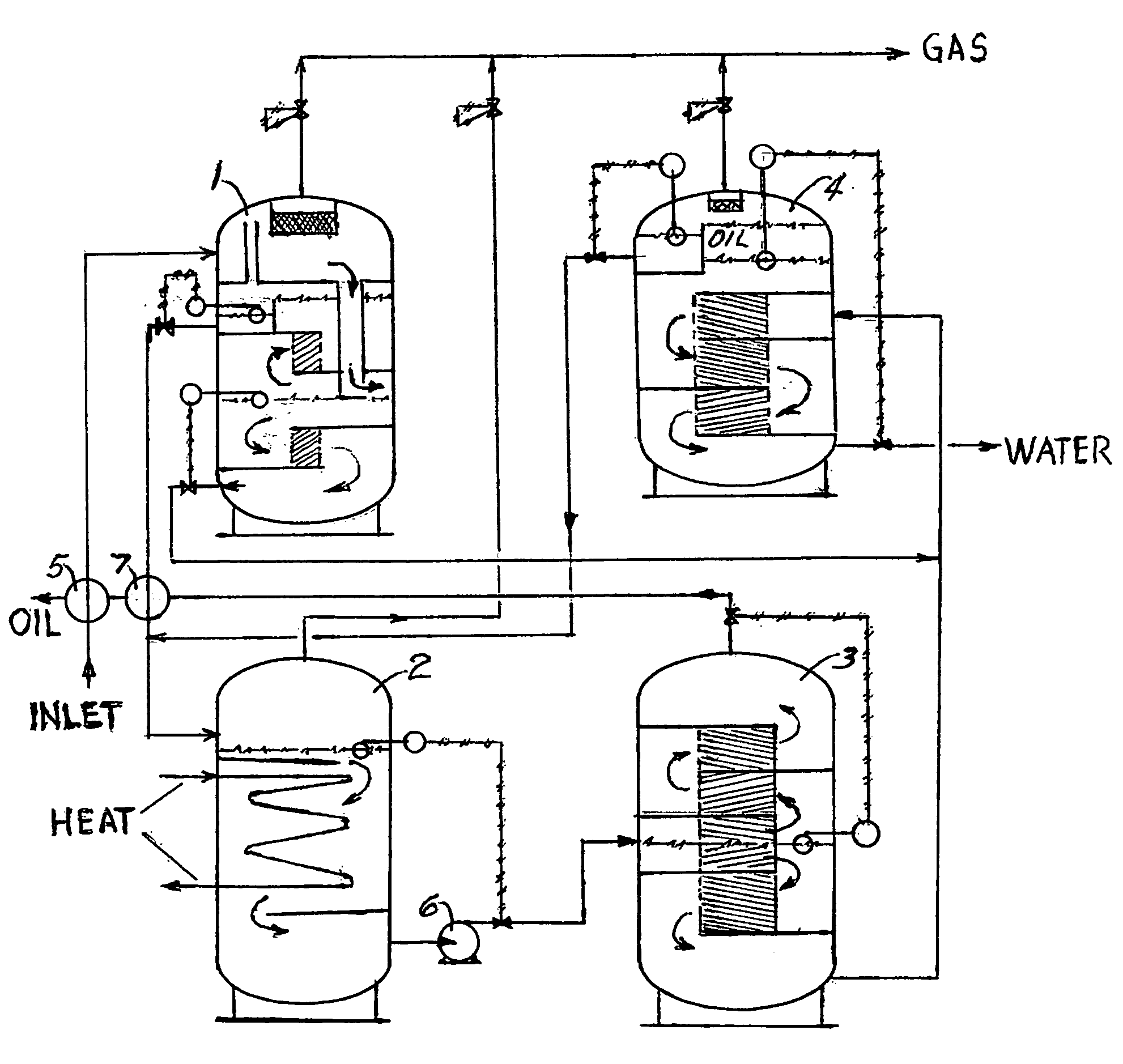
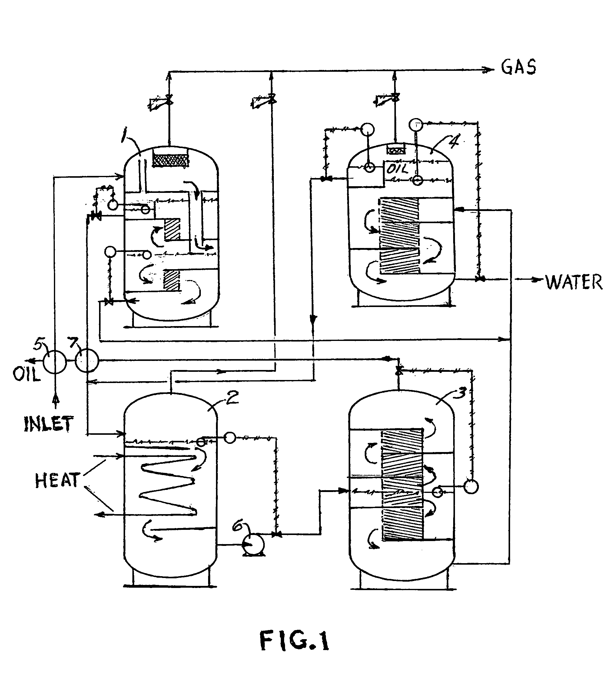
[0009]This method of processing oil produced from oil wells at water bound locations consists of four main vertical cylindrical process containment vessels, a Three Phase Production Separator 1, a Heating / Degassing Vessel 2, an Oil Dehydration Vessel 3 and a Water Degassing / De-Oiling Vessel 4. Other major ancillary components include a Cross Heat Exchanger 5, a Booster Pump 6 and possibly an Auxiliary Cross Heat Exchanger 7.

[0010]The oil flows from the oil well(s) through the Heat Exchanger 5 into the Separator 1 in which there is a baffle configuration that establishes a substantially horizontal flow pattern inside the Separator to enhance the separation efficiency. Within this Separator associated water and gas are separated from the oil.

[0011]The oil is delivered from the Separator to the Heating / Degassing Vessel 2 wherein the process pressure is reduced and the process temperature is elevated. This vessel is of a vertical configuration to mitigate the c...


PUM


Abstract

A method for processing oil from oil wells having water bound locations whereby it is necessary to place the process containment vessels upon host structures that are floating and subjected to a swaying motion caused by the wave action of the water in which the host structures float. The process containment vessels are of a vertical cylindrical configuration to minimize their footprint and to mitigate the effect of tilting on the spatial process geometry inside of the vessels and further the vessels contain internal baffles that create horizontal flow patterns inside of the vertical vessel for a more efficient gravity separation process.

Description

FIELD OF THE INVENTION[0001]This invention relates to methods for processing oil production from water bound oil wells wherein it is necessary to place the processing containment vessels upon floating host structures such as ships or floating platforms.BACKGROUND OF THE INVENTION[0002]When placing oil production process containment vessels upon floating host structures it is essential to have the containment vessels occupy the minimum amount of floor space and further to configure the containment vessels in such a way that the swaying and tilting that is inherent to the heaving and rolling motion of the floating host structure as it responds to the natural wave action of the water upon which it rests, will have the least possible detrimental effect on the process performance.[0003]Because the separating efficiency of containment vessels utilizing horizontal flow paths such as those described by my U.S. Pat. Nos. 5,865,992 and 5,902,483 is known to be superior to that of containment ...

Claims


Application Information

Patent Timeline
IPC IPC(8): B01D17/00B01D19/00B01D21/00E21B43/34
CPCB01D17/00B01D19/0042B01D19/0052B01D19/0057B01D19/0068B01D21/0027B01D21/0045B01D21/0066B01D21/009B01D21/02B01D21/2494E21B43/34B01D17/005B01D17/0211B01D21/0039B01D17/12
Inventor EDMONDSON, JERRY M.
Owner EDMONDSON TECH HLDG
Why Eureka
Try Eureka