Method for forming phosphor layer of gas discharge tube and method for fabricating phosphor layer supporting member

a technology of gas discharge tube and supporting member, which is applied in the manufacture of electric discharge tube/lamp, electrode system, and application of luminescent coatings, etc., can solve the problem of difficult fabrication of supporting members, and achieve the effect of easy formation of uniform phosphor films

Inactive Publication Date: 2005-11-29
SHINODA PLASMA
View PDF20 Cites 43 Cited by
  • Summary
  • Abstract
  • Description
  • Claims
  • Application Information

AI Technical Summary

Benefits of technology

[0009]According to the present invention, the phosphor layer is formed in the gas discharge tube by drawing the base material to fabricate the supporting member which is insertable in the gas discharge tube, forming the phosphor layer on the surface of the supporting member, and inserting into the gas discharge tube the phosphor layer supporting member having the phosphor layer formed thereon. The yield of the supporting member fabricated by the method of the present invention is higher than that of the supporting member fabricated by grinding. Compared with a method of forming a phosphor layer directly on an inner wall of a gas discharge tube, the method of the present invention can easily form a uniform phosphor film. Furthermore, since the phosphor layer can be baked outside the gas discharge tube, no contamination of a discharge gas by a residue of an organic component takes place at the baking of the phosphor layer.

Problems solved by technology

On the other hand, fabrication of the supporting member is not easy because the supporting member needs to be a structure which is slimmer than the small glass tube and almost the same as the small glass tube in length, and needs to have an almost the same expansion coefficient as that of the small glass tube.

Method used


Image

  • Method for forming phosphor layer of gas discharge tube and method for fabricating phosphor layer supporting member
  • Method for forming phosphor layer of gas discharge tube and method for fabricating phosphor layer supporting member
  • Method for forming phosphor layer of gas discharge tube and method for fabricating phosphor layer supporting member

Examples


Embodiment Construction

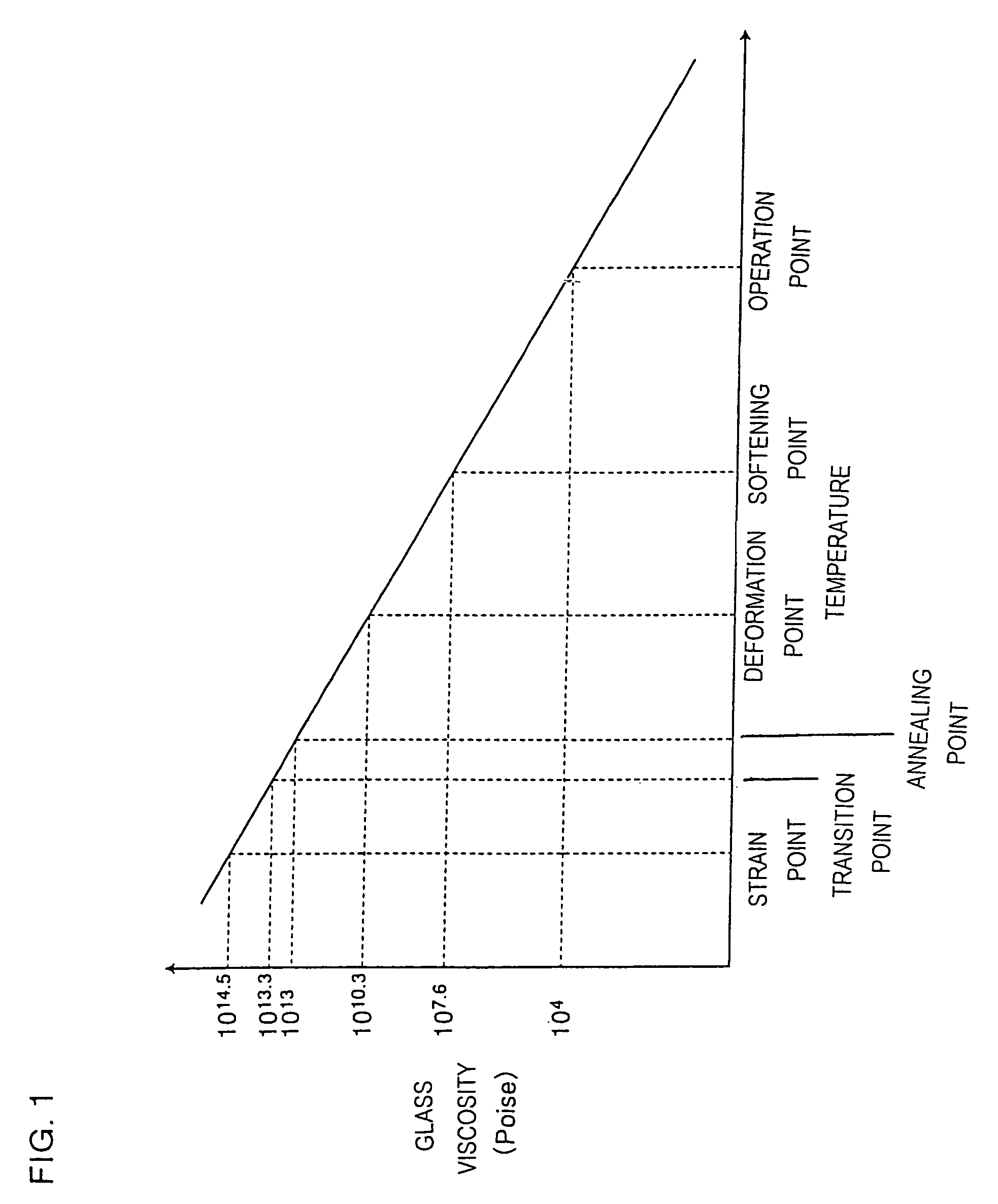
[0025]In the method for forming a phosphor layer of a gas discharge tube of the present invention, the phosphor layer is formed in the gas discharge tube by, drawing a base material to fabricate a supporting member for forming a phosphor layer thereon, forming the phosphor layer on the supporting member, and inserting into the gas discharge tube a phosphor layer supporting member having the phosphor layer formed thereon. The phosphor layer supporting member to be fabricated by the present invention can be used suitably for a gas discharge tube for display comprising a small tube having a diameter of about 0.5–5 mm. The present invention provides methods for forming a phosphor layer and for fabricating a phosphor layer supporting member that are suitable for such a gas discharge tube for display as described above.

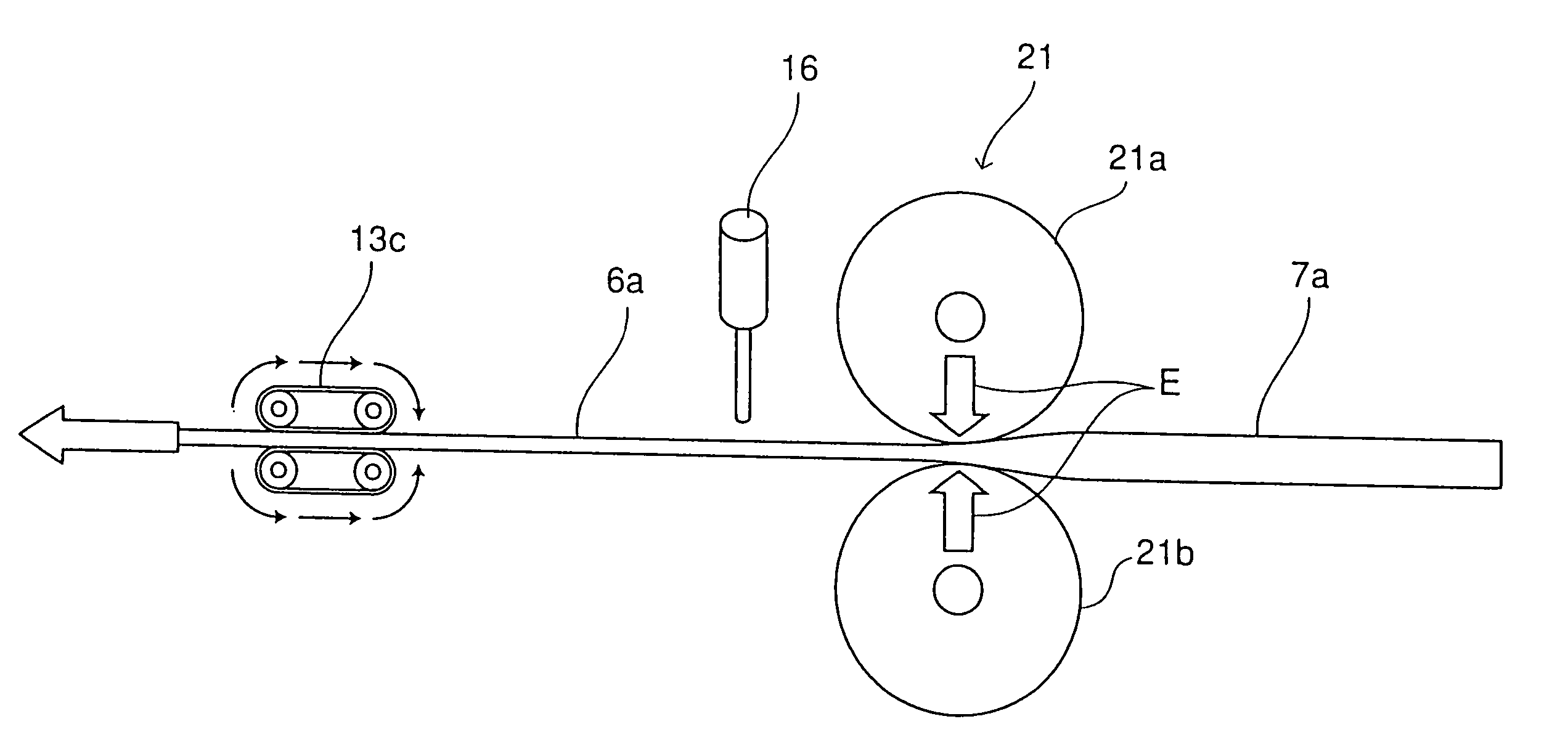
[0026]The supporting member used in the phosphor layer formation method of the present invention is fabricated as follows. As a preliminarily step, a large base material ha...


PUM

PropertyMeasurementUnit
internal diameteraaaaaaaaaa
diameteraaaaaaaaaa
viscosityaaaaaaaaaa

Abstract

A phosphor layer is formed efficiently in a gas discharge tube by drawing a mother material to fabricate a supporting member which is insertable in a small glass tube used for a gas discharge tube, forming a phosphor layer on the supporting member, and inserting and placing the supporting member in the small glass tube.

Description

[0001]This application is a continuing application, filed under 35 U.S.C. §111 (a), of International Application PCT / JP02 / 09385, filed Sep. 12, 2002, it being further noted that foreign priority benefit is based upon Japanese Patent Application 2001-280187, filed Sep. 14, 2001.TECHNICAL FIELD[0002]The present invention relates to a method for forming a phosphor layer of a gas discharge tube and a method for fabricating a phosphor layer supporting member. More particularly, the present invention relates to a method for forming a phosphor layer of a gas discharge tube comprising a small glass tube having an internal diameter of about 0.5–5 mm, and to a method for fabricating a phosphor layer supporting member which is insertable in the gas discharge tube and which has a phosphor layer formed on its surface.BACKGROUND ART[0003]A display device for displaying an arbitrary image is known, in which a plurality of gas discharge tubes each comprising a small glass tube having an internal di...

Claims


Application Information

Patent Timeline
Patent Type & Authority Patents(United States)
IPC IPC(8): B05D5/06B05D7/22C03B23/045C03B23/047C03B23/049C03B23/055C03C17/00H01J9/22H01J9/227H01J11/12H01J11/18H01J11/22H01J11/24H01J11/26H01J11/34H01J11/42
CPCC03B23/045C03B23/047C03B23/049C03B23/055C03C17/003H01J9/22
Inventor TOKAI, AKIRAYAMADA, HITOSHIISHIMOTO, MANABUSHINODA, TSUTAE
Owner SHINODA PLASMA
Why Eureka
Try Eureka