Method and device for decoupling an actuator from a gear

a gear and actuator technology, applied in the field of automotive, can solve the problems of motors that cannot be adjusted at all, and achieve the effect of convenient holding and cost-effectiveness

Inactive Publication Date: 2005-11-29
ROBERT BOSCH GMBH
View PDF6 Cites 5 Cited by
  • Summary
  • Abstract
  • Description
  • Claims
  • Application Information

AI Technical Summary

Benefits of technology

[0011]In the energized state, current is carried through the windings of the electric actuator; the windings are therefore easily held in the operating position by the permanent magnet against the force of a loaded throwout element. Operating position sensors and end position sensors can be provided on the electric actuator without having to make costly modifications to said actuator.
[0012]With this exemplary embodiment of the object obtained according to the invention, a space-saving variant can be created by arranging the downstream gear on the armature shaft; the pole pot-type extension, i.e., the extension of the housing of the part of the electric actuator that houses the stator and the armature shaft, can be equipped with a bearing that also supports axial loads, so that only slight changes must be made to existing systems, and the object proposed according to the invention can be realized cost-effectively.

Problems solved by technology

If the power to the electric drive designed as a DC motor fails, the motor can either not be adjusted at all, or only by using relatively strong forces.

Method used


Image

  • Method and device for decoupling an actuator from a gear
  • Method and device for decoupling an actuator from a gear
  • Method and device for decoupling an actuator from a gear

Examples


Embodiment Construction

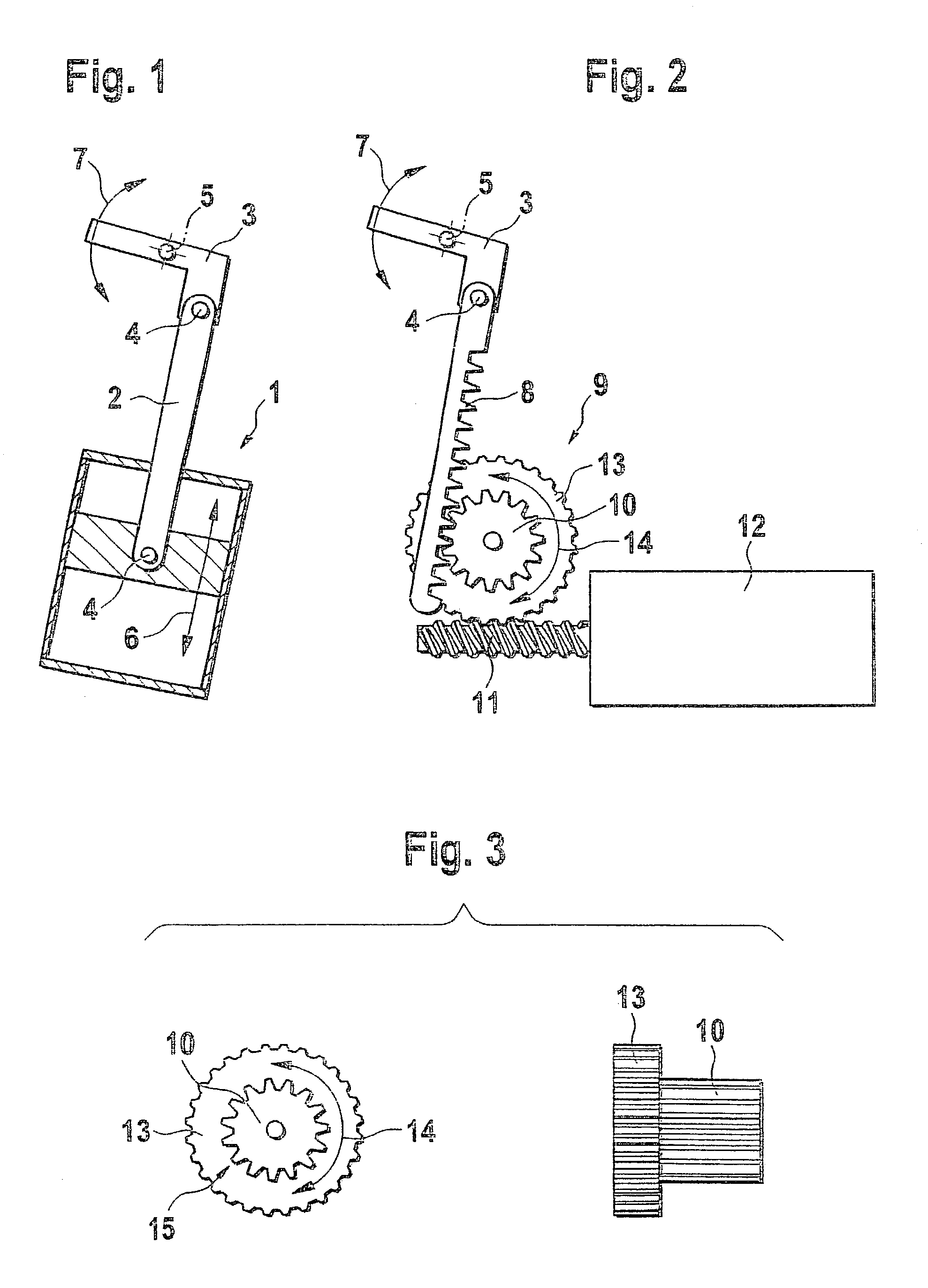
[0024]Control drives known in the related art are shown in the illustrations in FIGS. 1 and 2.

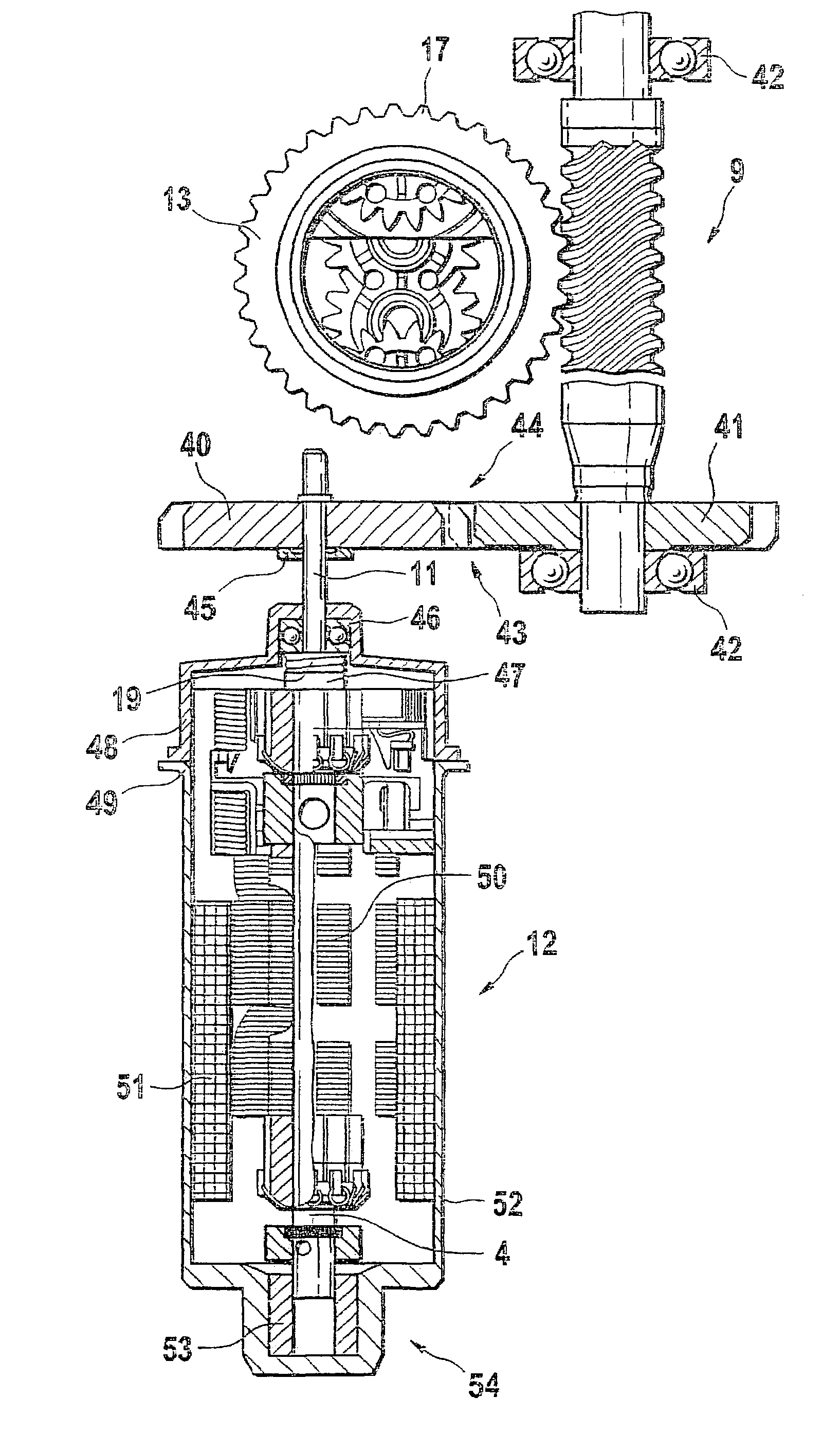
[0025]Based on the illustration according to FIG. 1 as well, a piston / cylinder arrangement 1 is known in which a piston moves up and down in a closed cylinder in the direction of motion 6. At the pivot point 4, a coupling element 2 is hinge-mounted on the piston capable of being moved in the cylinder, and it is supported hingedly on a swiveling lever 3 at its pivot point 4 furthest away from the piston. The swiveling lever 3—which is designed in the shape of an L in the illustration according to FIG. 1—is capable of being swivelled around a pivot axis and travels the pivot path illustrated with the double arrow 7. The illustration according to FIG. 2 can be found in an electric drive 12 that cooperates with a worm gear 13 by means of an armature shaft 11 on which a worm can be integrally molded, for example. The worm gear 13 is equipped with worm-gear external teeth corresponding to the tee...


PUM


Abstract

The invention is based on a control drive for operating drive components or adjusting components in motor vehicles. The control drive comprises an electric actuator (12) that acts on force-transmitting elements (19, 13; 40, 41). With these, the adjusting motion is transmitted to the drive or adjusting components to be adjusted. A throwout element (19) is provided that interrupts the transmission of force by the force-transmitting elements (10, 13; 40, 41) in the de-energized state (23, 55) of the electric actuator.

Description

BACKGROUND OF THE INVENTION[0001]In the automotive industry, servomotors are often used in commercial vehicles and passenger cars to operate the clutch or as transmission servomotors, for example. Electric servomotors can also be used on components such as exhaust-gas turbochargers to supercharge mixture-compressing internal combustion engines. Exhaust-gas turbochargers were previously operated via the vacuum detected in the intake manifold; a method of operating such exhaust-gas turbochargers in automatable fashion is given by providing an electric drive.RELATED ART[0002]Servomotors that are typically used as clutch or gear actuators comprise a DC electric motor, on the armature shaft of which a worm is integrated, which said worm meshes with a worm gear; further gear stages can be provided as well. A linear or a rotary motion can be produced using the DC electric motor.[0003]In addition, DC motors can be used as servomotors on add-on components of internal combustion engines, on a...

Claims


Application Information

Patent Timeline
Patent Type & Authority Patents(United States)
IPC IPC(8): F02N15/04F16H3/20H02K7/06H02K7/116H02K7/12
CPCF02N15/046F16H3/20H02K7/125H02K7/116H02K7/06Y10T74/19H02K2201/18
Inventor NEUBAUER, ACHIMASCHOFF, JOERGDILGER, WERNERPIERENKEMPER, ROLFBOLZ, MARTIN-PETERMOENCH, JOCHEN
Owner ROBERT BOSCH GMBH
Why Eureka
Try Eureka