Variable data width converter

Inactive Publication Date: 2005-11-29
XILINX INC
View PDF14 Cites 41 Cited by
  • Summary
  • Abstract
  • Description
  • Claims
  • Application Information

AI Technical Summary

Benefits of technology

[0011]The present invention will be more fully underst

Problems solved by technology

Yet another factor is the size con

Method used


Image

  • Variable data width converter
  • Variable data width converter
  • Variable data width converter

Examples


Embodiment Construction

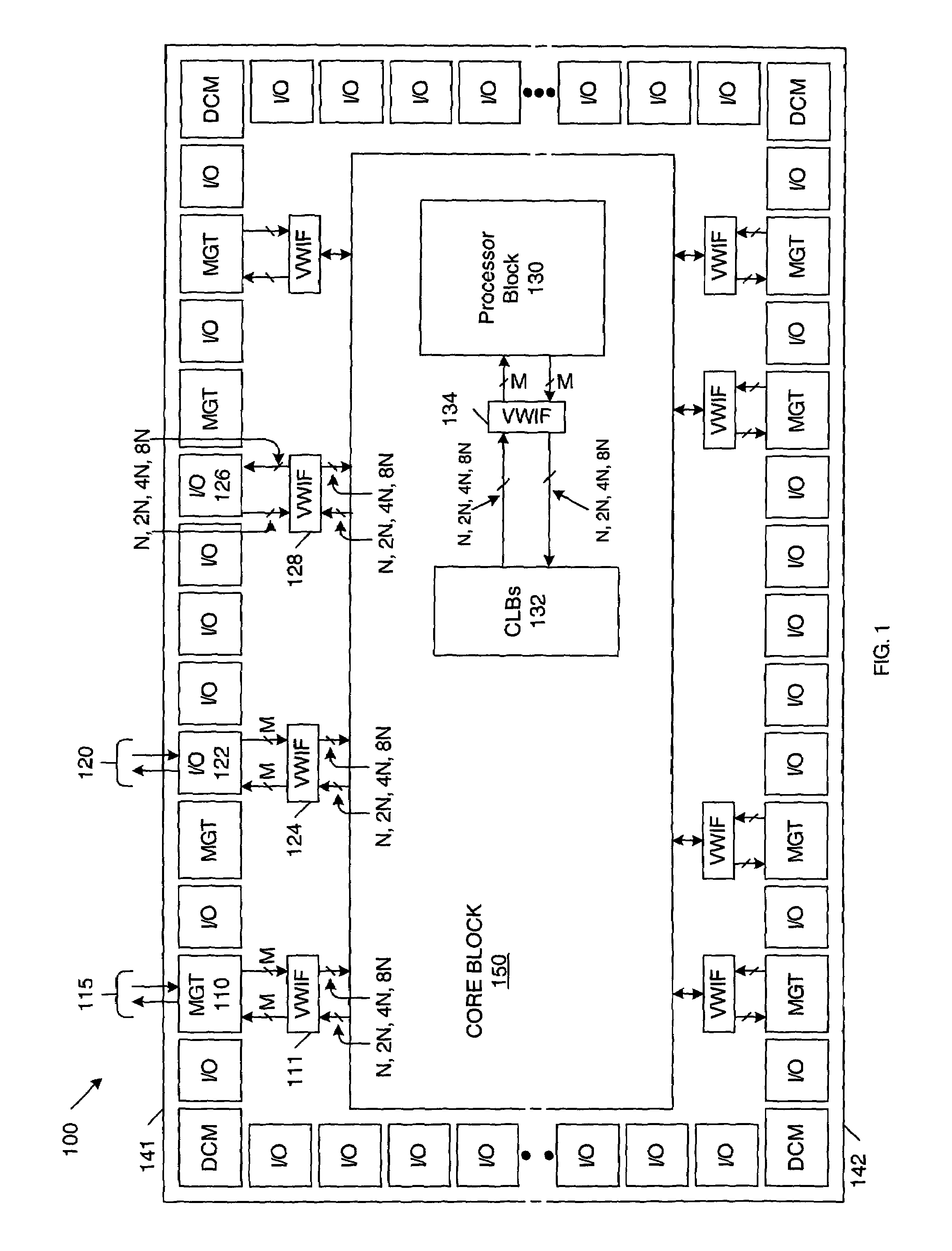
[0025]FIG. 1 is a block diagram of a programmable logic device (PLD) 100 in accordance with one embodiment of the present invention. In the described embodiment, PLD 100 is a field programmable gate array (FPGA) that includes select I / O blocks (labeled I / O), digital clock managers (labeled DCM) and multi-gigabit transceivers (labeled MGT) located around the perimeter of the device. Each MGT includes a full-duplex differential data channel, such as channel 115. PLD 100 also includes core block 150, which includes an array of configurable logic blocks (CLBs), programmable routing circuitry, and optional embedded hardwire circuitry, for example, processor block 130, in the described embodiment. Variable-width interface circuits (labeled VWIF) are located between each of the MGTs and core block 150. Select I / O blocks I / O, digital clock managers DCM and core block 150 are well known to those of ordinary skill in the art. These conventional elements of PLD 100 are described in detail in “...


PUM


Abstract

An integrated circuit (IC) with programmable circuitry having programmable functions and programmable interconnections. The IC further includes: a first module having an output with a first fixed data width or first variable data width; a second module having an input with a second fixed data width or a second variable data width; and a data width converter receiving data from the output of the first module and sending the data to the input of the second module, the data width converter configured to convert data from the first fixed data width or first variable data width to the second fixed data width or the second variable data width.

Description

BACKGROUND OF THE INVENTION[0001]1. Field of the Invention[0002]The present invention relates to an integrated circuit (IC) having circuitry with programmable functions and programmable interconnections. More specifically, the present invention relates to a method and apparatus for converting to and from variable-width data paths.[0003]2. Related Art[0004]In the past, multi-gigabit transceivers (MGTs) have not been included on programmable logic devices (PLDs) for various reasons, where a PLD is any IC which has programmable functions and programmable interconnections. However, commonly owned, copending U.S. patent application Ser. No. 10 / 090,250 filed on Mar. 1, 2002 entitled “High Speed Configurable Transceiver Architecture” by Suresh M. Menon et al., describes the manner in which MGTs can be included on a PLD, such as a field programmable gate array (FPGA). It would therefore be desirable to optimize the data paths between the core logic of a PLD and the MGTs located on the PLD.[...

Claims


Application Information

Patent Timeline
IPC IPC(8): G06F13/40H03K19/177
CPCG06F13/4018
Inventor CORY, WARREN E.
Owner XILINX INC
Why Eureka
Try Eureka