
Pet tracking collar

a tracking collar and pet technology, applied in the field of tracking devices, can solve the problems of rapid corrosion and deterioration, rapid failure of lighting features, etc., and achieve the effect of preventing receiver overloading

Inactive Publication Date: 2005-11-29
SCIARRA MICHAEL
View PDF9 Cites 82 Cited by
  • Summary
  • Abstract
  • Description
  • Claims
  • Application Information

AI Technical Summary

Benefits of technology

[0007]It is another object of the present invention to provide a system for lighting a pet collar that has improved visibility.
[0009]It is yet another object of the present invention to provide a pet tracking system that is durable and that has an enhanced life span.
[0018]The radio frequency signal receiver may include at least one directional antenna to determine the relative direction of the radio frequency signal from the transmitter. The radio frequency signal receiver may also include, either with or without the directional antenna, an alarm to signal when a radio frequency signal from the transmitter decreases below a predetermined strength. Preferably, the radio frequency signal receiver includes a signal attenuator adapted to automatically adjust gain as the transmitter approaches the receiver to prevent overloading of the receiver.

Problems solved by technology

Previous attempts at constructing these types of collars suffer from generally poor lighting, a large power drain (which requires large batteries and / or frequent battery replacement), and an inability to withstand constant motion and strain, which can break the wires utilized in their construction leading to rapid failure of the lighting feature.
Further, attempts at sealing the electronic circuit, battery and exposed portion of the LED lights have led to rapid failures.
This failure mode was caused because at least one end, LED light protrusions to the exterior of the collar, and wired battery connections were exposed and opened to the environment, which led to rapid corrosion and deterioration.
Products of this nature tend to have very brief life spans, and these failure modalities have not been adequately addressed.

Method used


Image

  • Pet tracking collar
  • Pet tracking collar
  • Pet tracking collar

Examples


Embodiment Construction

)

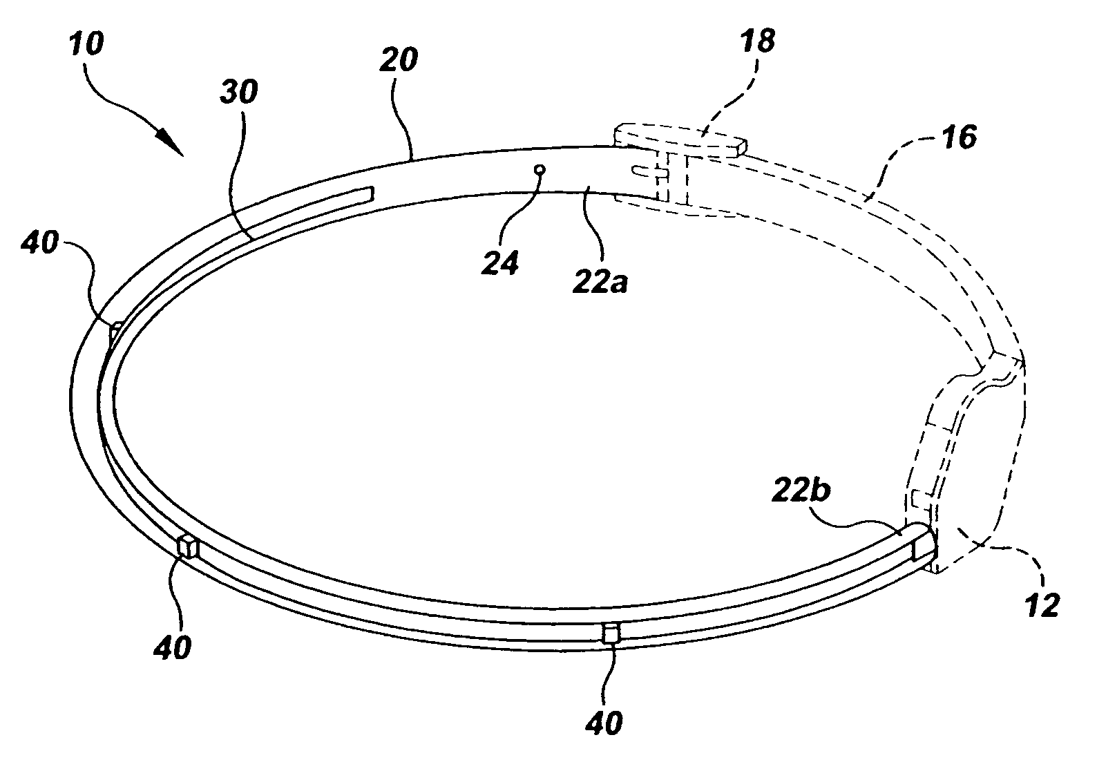
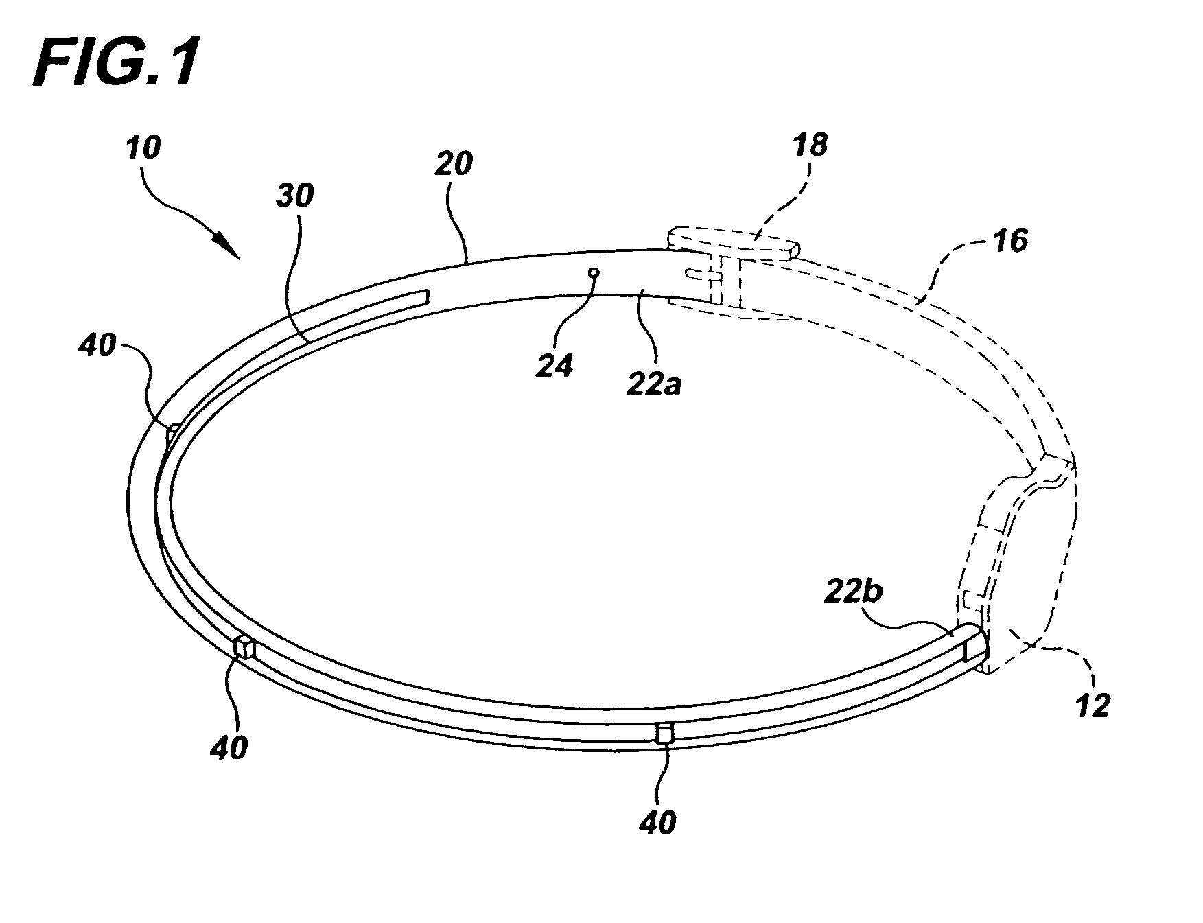
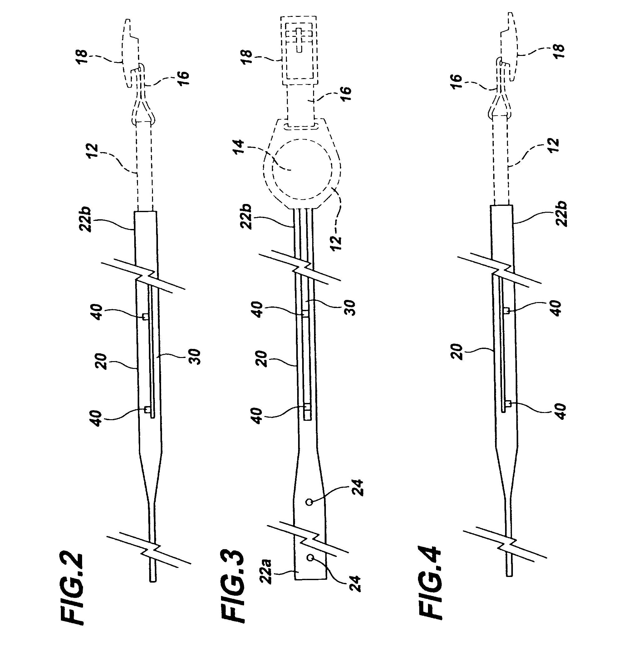
[0036]In describing the preferred embodiment of the present invention, reference will be made herein to FIGS. 1–13 of the drawings in which like numerals refer to like features of the invention.

[0037]This invention is directed to a lighted pet tracking collar that operates on a watch-type battery to render animals visible during the night that further incorporates an AM, FM, UHF or other wireless transmitter configured so as to enable location of a lost or out of sight animal through the use of a small direction-indicating handheld receiver. The preferred embodiment of the pet tracking collar 10 is depicted in FIGS. 1–11, and includes a battery housing 12 having attached on one end a flexible nylon strap 16 and buckle 18, and on the opposite end a flexible clear plastic tubing 20 having a compressed and heat-sealed free end 22a with an opening 24 for engagement with the buckle tab. Membrane switch 11 on the back of housing 12 (FIGS. 5 and 11) is connected to the microprocessor and ...


PUM


Abstract

A pet tracking collar comprises a length of clear flexible tubing having a fastener adapted to fasten around the pet. Hermetically sealed within the tubing is an electrical ribbon cable extending through the length thereof. A plurality of light-emitting diodes, visible through the clear tubing, are wirelessly connected at spaced intervals to the cable. The tracking collar also includes an antenna within the electrical ribbon cable, and a radio transmitter secured to the cable adapted to transmit a radio frequency signal. The cable is secured within the flexible tubing such that strain along the length of the tubing is not transmitted to the cable therein. The collar's battery compartment has sufficient clearance between the battery and walls of the battery compartment to shed water after the collar is wetted. A radio frequency signal receiver determines direction or distance of the collar with respect to the receiver.

Description

BACKGROUND OF THE INVENTION[0001]1. Field of the Invention[0002]The present invention relates to tracking devices and, in particular, to a pet collar that incorporates both light and radio tracking capabilities.[0003]2. Description of Related Art[0004]Previous attempts to provide lighted pet collars generally have fallen into three categories. In one category, there have been collars that have several light emitting diodes (LED) placed around the collar, and those LEDs have been traditional wide dispersion diodes which spread the energy over 140° or more and typically have only a 100–120 mcd brightness level. In another category, there have been collars that have employed a pendant-type of tag, i.e., one that lights up and hangs from the collar, but is not part of the collar itself. In a third category, there have been collars that use electro-luminescent displays that are sewn or otherwise attached to the collar.[0005]Previous attempts at constructing these types of collars suffer ...

Claims


Application Information

Patent Timeline
IPC IPC(8): A01K15/02A01K27/00G08B1/08G08B23/00H04Q7/00
CPCA01K15/023A01K27/006A01K27/009G08B21/0288
Inventor SCIARRA, MICHAEL
Owner SCIARRA MICHAEL
Learn More