Phase compensated field-cancelling nested loop antenna

a phase-compensated loop antenna and field-cancelling technology, applied in the field of loop antennas, can solve the problems of system performance degradation, system performance degradation of system utilizing such antennas, and system performance degradation of such antennas, and achieve the effect of reducing current variation

Inactive Publication Date: 2005-11-29
TYCO FIRE & SECURITY GMBH
View PDF12 Cites 54 Cited by
  • Summary
  • Abstract
  • Description
  • Claims
  • Application Information

AI Technical Summary

Benefits of technology

[0012]According to a further aspect of the invention, there is provided a method of reducing current variation along a length of a loop antenna including: providing an excitation current to the loop antenna; and controlling the excitation current along the length of the loop antenna by providing at least one phase compensation element along the length of the loop antenna.

Problems solved by technology

This leads to degradation in performance of systems utilizing such antennas.
Again, this leads to degradation in performance of systems utilizing such antennas, and in particular is highly undesirable for field-canceling antennas which rely on even field distribution for canceling affects.
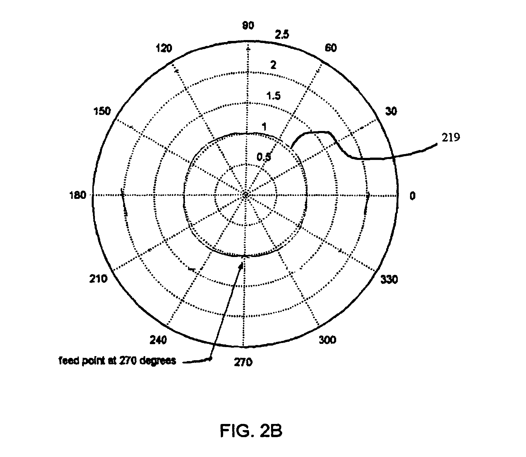
These current variations lead to degradation in performance of systems utilizing such antennas.
In systems wherein the excitation frequency is fixed, e.g. in some EAS and RFID systems, current variations associated with exceeding an antenna length of 1 / 10th of the operating wavelength place a practical limit on the physical length of the loop antenna.
Limited antenna length limits the effective range of such antennas.
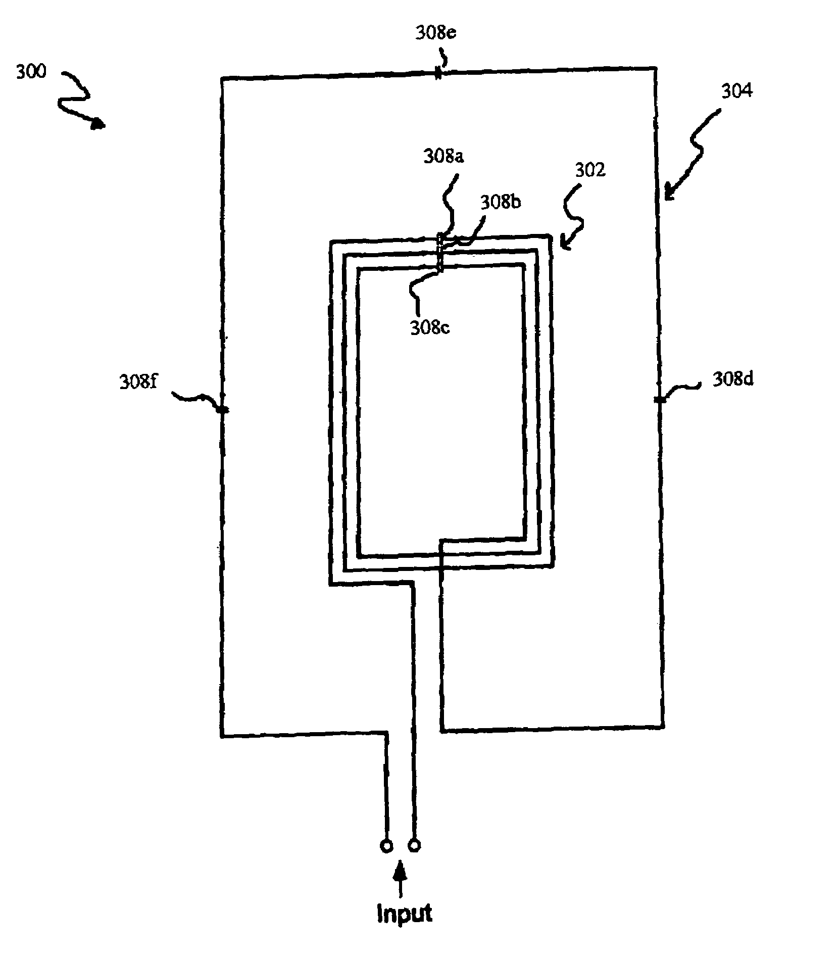
As such, the range of an inner loop antenna in a nested loop configuration is also limited.

Method used


Image

  • Phase compensated field-cancelling nested loop antenna
  • Phase compensated field-cancelling nested loop antenna
  • Phase compensated field-cancelling nested loop antenna

Examples


Embodiment Construction

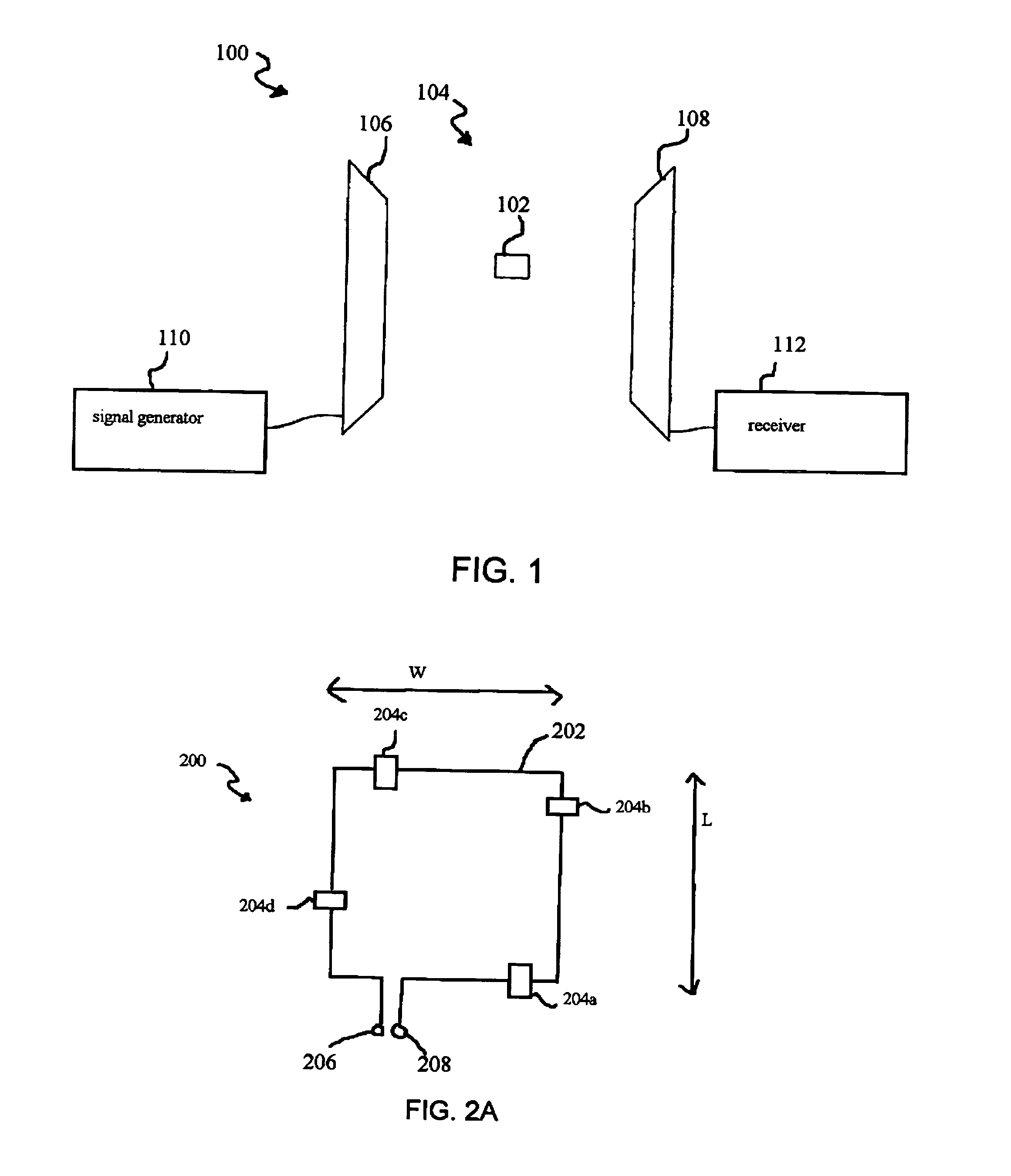
[0018]The present invention will be described herein in connection with various exemplary embodiments thereof associated with EAS systems. The present invention may, however, be incorporated into a wide variety of loop antenna systems and configurations. For example, the invention has utility in connection with RFID systems. Those skilled in the art will recognize that an RFID system utilizes RFID markers or tags to track articles for various purposes such as inventory. The RFID marker may store data associated with the article, and an RFID reader may scan the RFID marker to read the data by transmitting an interrogation signal at a known frequency. The RFID reader may contain a phase compensated loop antenna consistent with the invention. In fact, the present invention may be advantageously employed, without departing from the spirit and scope of the invention, in any loop antenna system wherein it is useful or desired to reduce current variation along the length of the loop. It is...


PUM


Abstract

A phase compensated loop antenna having phase compensation elements distributed along the length thereof. The phase compensation elements compensate for current variations along the antenna length resulting from increasing the length of the antenna. A nested loop configuration incorporating at least one phase compensated loop antenna is also provided.

Description

FIELD OF THE INVENTION[0001]The present invention relates to loop antennas, and, in particular, to phase compensated loop antennas that may be utilized in a variety of systems, such as electronic article surveillance (EAS) and radio frequency identification (RFID) systems.BACKGROUND OF THE INVENTION[0002]A loop antenna may be utilized in a variety of systems, including, for example, EAS and RFID systems. An excitation source may provide current to, or induce current in, the loop antenna at a particular excitation frequency. The excitation source may include a tuning capacitor, where the value of the capacitor is used to set the excitation frequency. Current flowing along the length of the loop antenna generates an electromagnetic field in proportion to the current flow. If the current flow through the antenna exhibits wide variances, then the resulting electromagnetic field will exhibit corresponding variances. This leads to degradation in performance of systems utilizing such anten...

Claims


Application Information

Patent Timeline
Patent Type & Authority Patents(United States)
IPC IPC(8): G06K17/00G06K7/08H01Q7/00H01Q21/29
CPCG06K7/10336G08B13/2471G08B13/2474H01Q7/00H01Q21/29
Inventor COPELAND, RICHARD L.SHAFER, GARY MARK
Owner TYCO FIRE & SECURITY GMBH
Why Eureka
Try Eureka