Data transmission apparatus for transmitting ATM data streams

a data transmission apparatus and data technology, applied in transmission, time-division multiplexing selection, dot-and-dash system, etc., can solve the problems of low performance, high processing system requirements, and low cost of integrated circuit sar engin

Inactive Publication Date: 2005-11-29
STMICROELECTRONICS LTD
View PDF50 Cites 10 Cited by
  • Summary
  • Abstract
  • Description
  • Claims
  • Application Information

AI Technical Summary

Benefits of technology

[0032]Preferably the data stream control memory stores a pointer variable for each data stream and the data transmission unit prefer

Problems solved by technology

This imposes very heavy demands on the processing systems that are to perform the transmitting and receiving operations, especially the segmentation of messages into parts and the reassembly of those parts.
Current systems fall generally into two categories, having the following characteristics:Hardware-based designsVery fast dedicated SAR engines (typically 155/622 Mbits/s)Large silicon areasExpensive, and although they are hardware-based systems they often still require a microprocessor for control purposesComplicated control registers and memory management data structures defined in hardwareInflexible, which makes it difficult to adapt them to rapidly evolving new standards and marketsSoftware/Processor-based designsRelatively slow (usually sub 20 Mbits/s)Can be inexpensive with cheap RISC (reduced instruction set computing) processors, but become uneconomic in embedded s

Method used


Image

  • Data transmission apparatus for transmitting ATM data streams
  • Data transmission apparatus for transmitting ATM data streams
  • Data transmission apparatus for transmitting ATM data streams

Examples


Embodiment Construction

Basic System Architecture

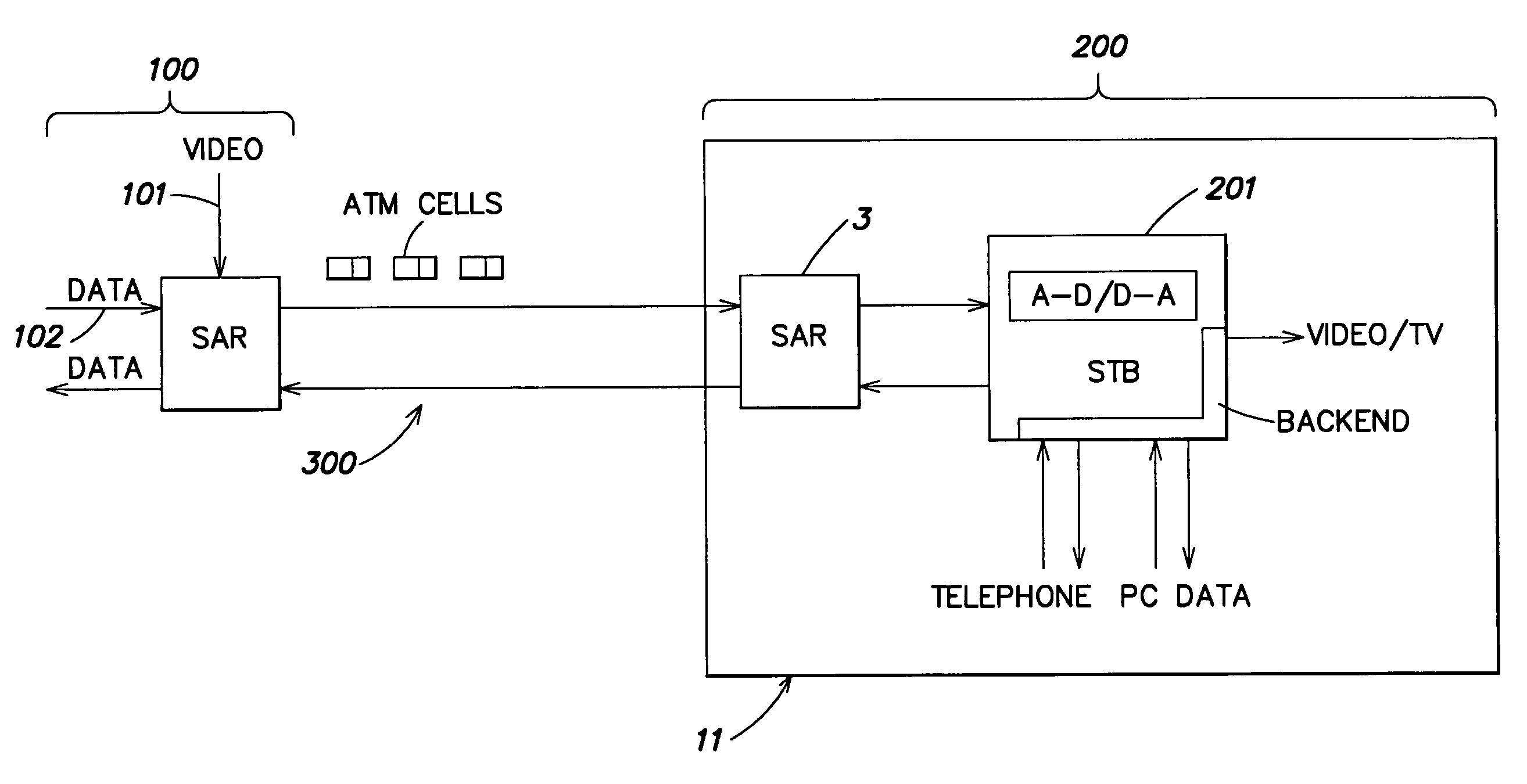
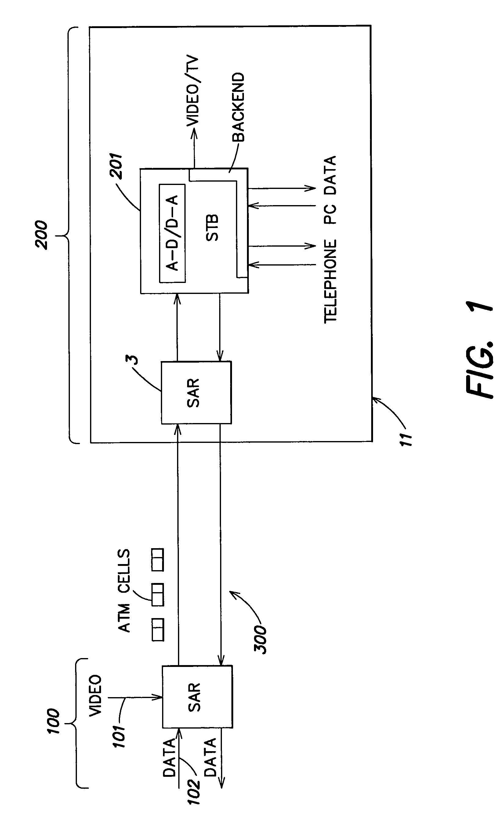
[0057]FIG. 1 shows an overall schematic view of a system for transmitting and receiving data. The system comprises a network end shown generally at 100, a terminal end shown generally at 200 and a bi-directional communications link 300 (which could, for example be provided by a telephone network, a dedicated cable connection or a radio link) between the two ends. Incoming video and other data streams 101, 102 are segmented at the network end and transmitted along the link 300 as ATM cells. These cells each contain a part of a message and have cell content information prepended to them. This cell content information indicates (among other things) which message the cell forms part of. When the cells arrive at the terminal end 200, which in this example is a personal system 11, they are re-assembled in the SAR engine 3 and sent to an STB data processing unit 201. This converts the messages into a form suitable for outputting to other equipment: for example, by ...


PUM


Abstract

A data reception unit for receiving a plurality of data streams over a data channel, the data streams being received as amounts of data and each amount of data comprising a data portion including data from a data stream and an identity portion identifying that data stream, the data reception unit comprising: a data stream memory comprising a plurality of data stream storage areas, each for storing data from a respective one of a set of the data streams, and an escape buffer; a first storage information memory for holding first storage information for facilitating storage in the respective data stream storage area of data from the set of the data streams; and a data storage controller for, for each received amount of data, receiving the identity portion of the amount of data and performing a storage operation comprising: accessing the first storage information memory; and if the first storage information memory holds first storage information for the data stream identified by the identity portion, storing the data portion of the amount of data in the data stream storage area corresponding to that data stream; and if the first storage information memory does not hold first storage information for the data stream identified by the identity portion, storing the data portion of the amount of data in the escape buffer; and a processing unit connected to the escape buffer for performing an assembly operation comprising executing steps to assemble the information stored in the escape buffer into respective data streams.

Description

FIELD OF THE INVENTION[0001]The present invention relates to the transfer of data, for example the transmission of multiple data messages over a single transmission medium and the conversion of those messages into a form suitable for transmission.BACKGROUND OF THE INVENTION[0002]There is a growing market in the field of digital communication. An increasing number of households have equipment to receive digital television, satellite and cable television, telephony and internet services. Telephony systems and the internet are interactive systems over which people can send and receive information and other digital communication systems are increasingly tending towards interactivity, for example as video-on-demand systems are introduced.[0003]Video, audio and other information (e.g. internet services), all hereinafter referred to as “data”, can be transmitted along a number of transmission media, for example over electrical or optical cable or via radio. The data can be considered to be...

Claims


Application Information

Patent Timeline
IPC IPC(8): H04L12/54H04L12/70H04Q11/04
CPCH04L12/5602H04Q11/0478H04L2012/5658H04L2012/5679
Inventor RICHARDS, NEILPANESAR, GAJINDER SINGHCAREY, JOHNTHOMPSON, PETER
Owner STMICROELECTRONICS LTD
Why Eureka
Try Eureka