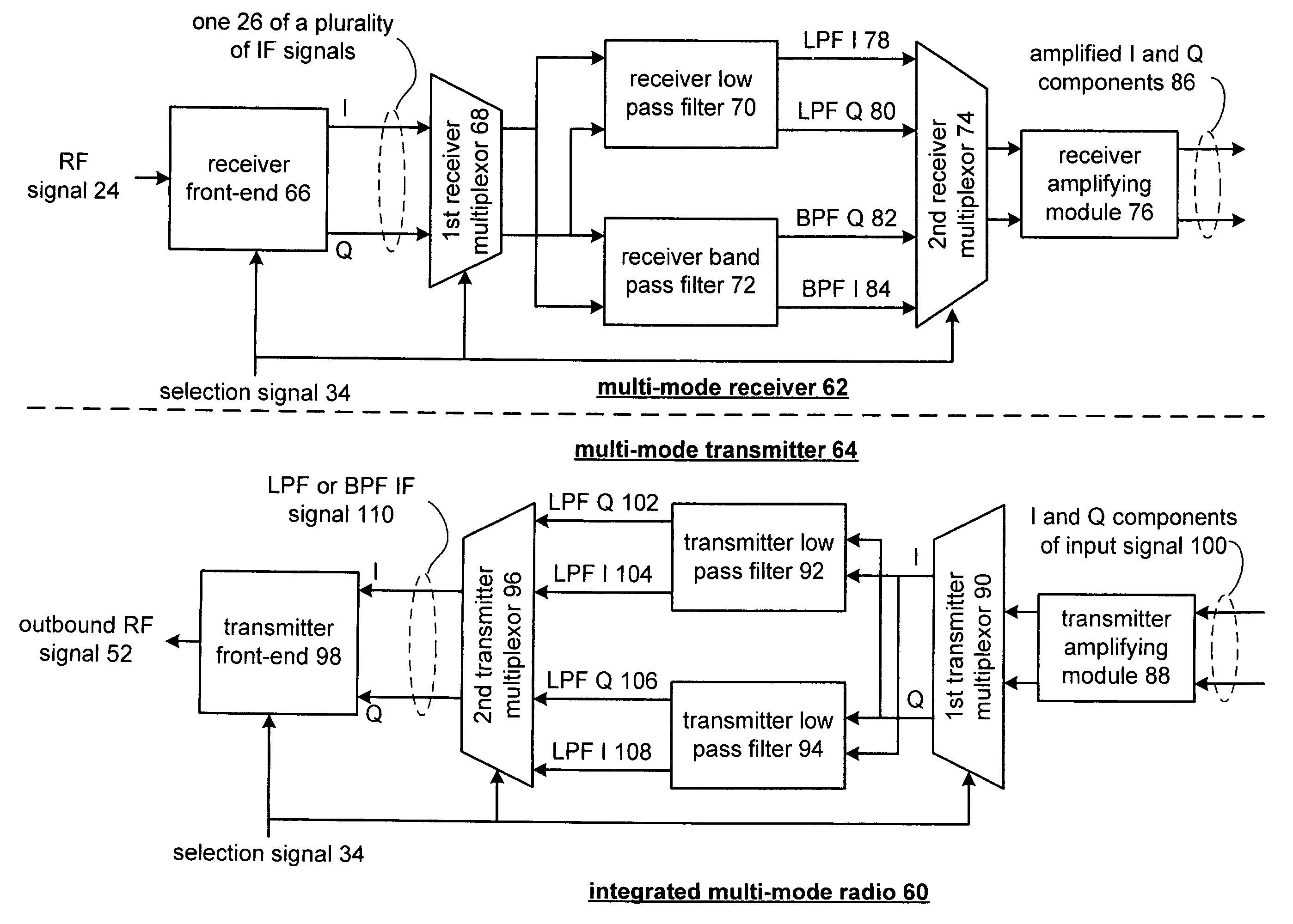
Integrated multimode radio and components thereof
- Summary
- Abstract
- Description
- Claims
- Application Information
AI Technical Summary
Problems solved by technology
Method used
Image
Examples
Embodiment Construction
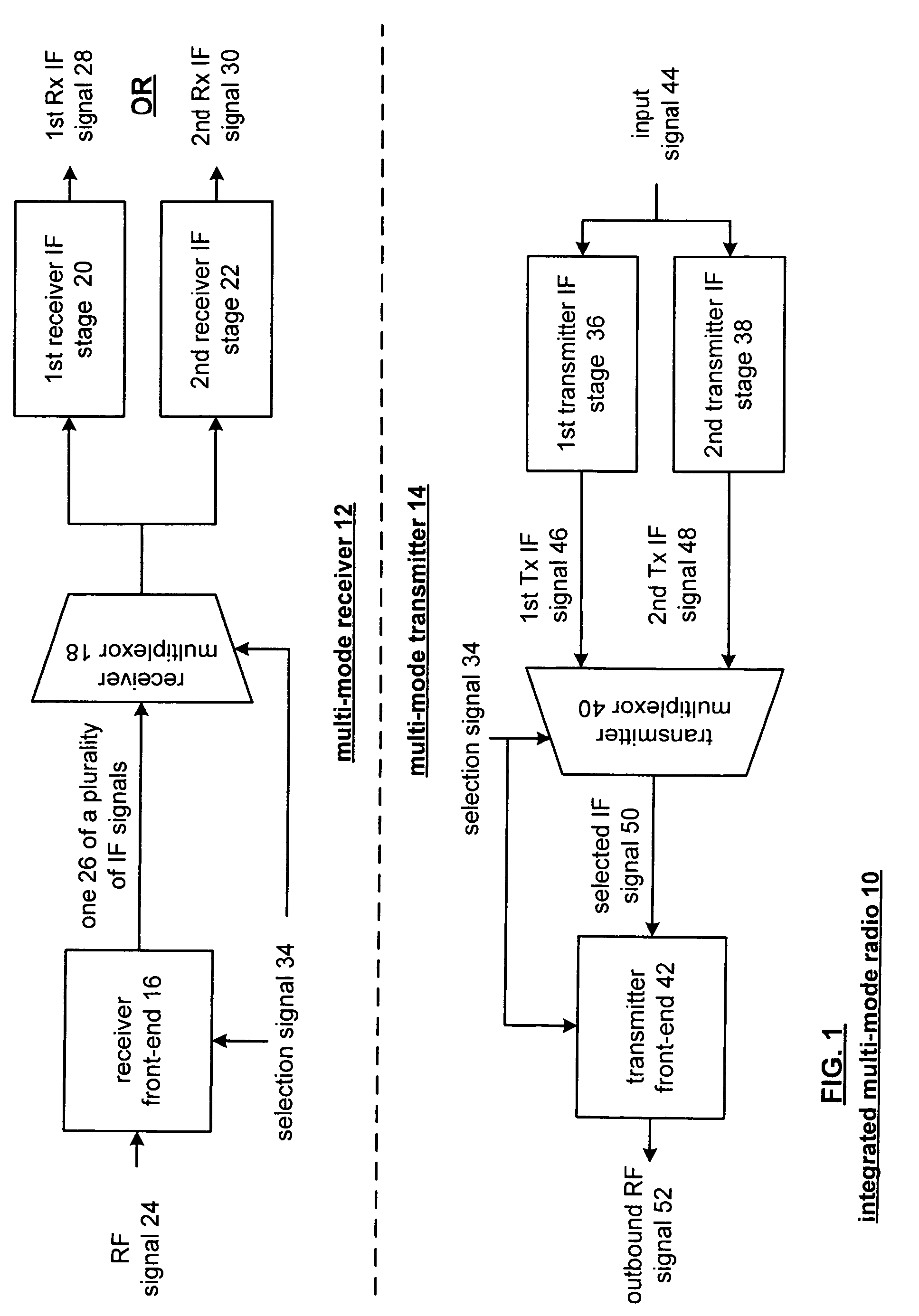
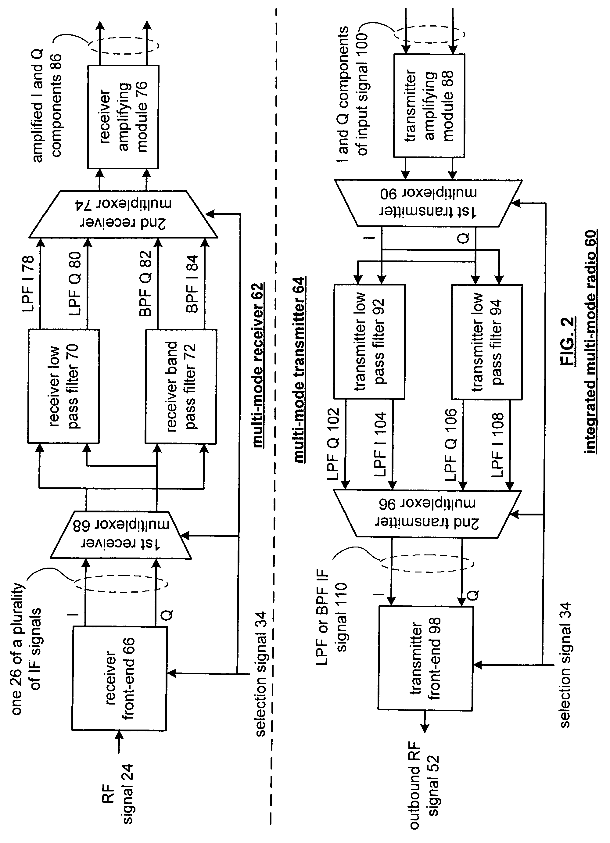
[0018]FIG. 1 illustrates a schematic block diagram of an integrated multimode radio 10 that includes a multimode receiver 12 and a multimode transmitter 14. The multimode receiver 12 includes a shared receiver front-end 16, a receiver multiplexor 18, and a plurality of receiver IF stages 20 and 22. The multimode transmitter 14 includes a shared transmitter front-end 42, a transmitter multiplexor 40, and a plurality of transmitter IF stages 36 and 38.
[0019]The shared receiver front-end 16 receives a radio frequency (RF) signal 24 and a selection signal 34. The selection signal 34 indicates the particular operational mode used to generate the RF signal 24. The RF signal 24 is a modulated signal in accordance with a particular operation mode, i.e., wireless communication standard. Such wireless communication standards include, but are not limited to, Bluetooth, IEEE 802.11a, IEEE 802.11b, analog mobile phone service (AMPS), digital AMPS (D-AMPS), global system for mobile (GSM), code di...
PUM
 Abstract
Description
Claims
Application Information
 - R&D
- Intellectual Property
- Life Sciences
- Materials
- Tech Scout
- Unparalleled Data Quality
- Higher Quality Content
- 60% Fewer Hallucinations
Browse by: Latest US Patents, China's latest patents, Technical Efficacy Thesaurus, Application Domain, Technology Topic, Popular Technical Reports.
© 2025 PatSnap. All rights reserved.Legal|Privacy policy|Modern Slavery Act Transparency Statement|Sitemap|About US| Contact US: help@patsnap.com


