
LNA with Programmable Linearity

a linearity and programmable technology, applied in the field of amplifiers, can solve the problems of reducing the gain in this manner, limiting the data rate at which information modulated on a signal can be accurately demodulated, and affecting the overall performance of the overall receiver, so as to reduce the gain of the lna

Active Publication Date: 2018-03-22
PSEMI CORP
View PDF0 Cites 25 Cited by
  • Summary
  • Abstract
  • Description
  • Claims
  • Application Information

AI Technical Summary

Benefits of technology

The patent describes a receiver front-end that can handle a wide range of signal levels and has a low noise figure. The front-end operates in multiple gain modes and has a constant current density through the amplifier FETs. The front-end uses a plurality of amplifier branches, each with a different weight to achieve the desired gain. A bank of input and output capacitors can be switched to ensure the same reactance at the input and output of the amplifier. A bank of gain control resistive elements can be added or subtracted to adjust the gain. A bank of output capacitors can be selected to ensure the same capacitive reactance at the output. A post fabrication variable gate to source capacitance can be used for post-tuning measurements.

Problems solved by technology

Any noise or distortion introduced by the LNA will cause a degradation in the overall receiver performance.
Limitations on the amount of gain that can be applied without imposition of excessive distortion by the front-end of the receiver can limit the data rate at which information modulated on a signal can be accurately demodulated from the signal once received.
However, there are several disadvantages to reducing the gain in this manner.
In addition, operating at lower LNA bias current severely degrades the input impedance matching, causing gain, linearity and noise figure degradation.
However, the resulting degradation in the noise figure makes it difficult to increase the input impedance for some gain modes, making it impractical in modes that require a low noise figure.
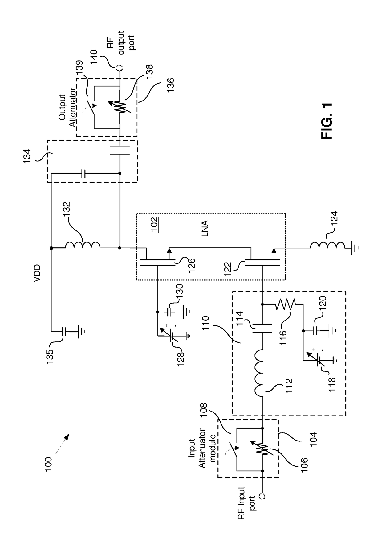
In addition, attenuator modules tend to add parasitic capacitance at the input and output, resulting in degradation in the input and output matching, which results in distortion and makes the LNA 102 less efficient.
This complicates the design and, as noted above, significantly increases the die area required to fabricate the LNA 102.

Method used


Image

  • LNA with Programmable Linearity
  • LNA with Programmable Linearity
  • LNA with Programmable Linearity

Examples


Embodiment Construction

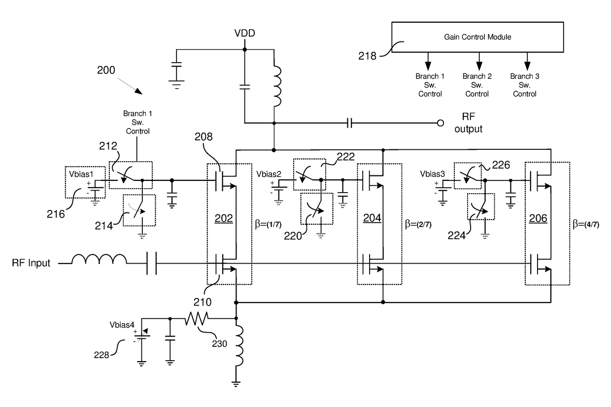
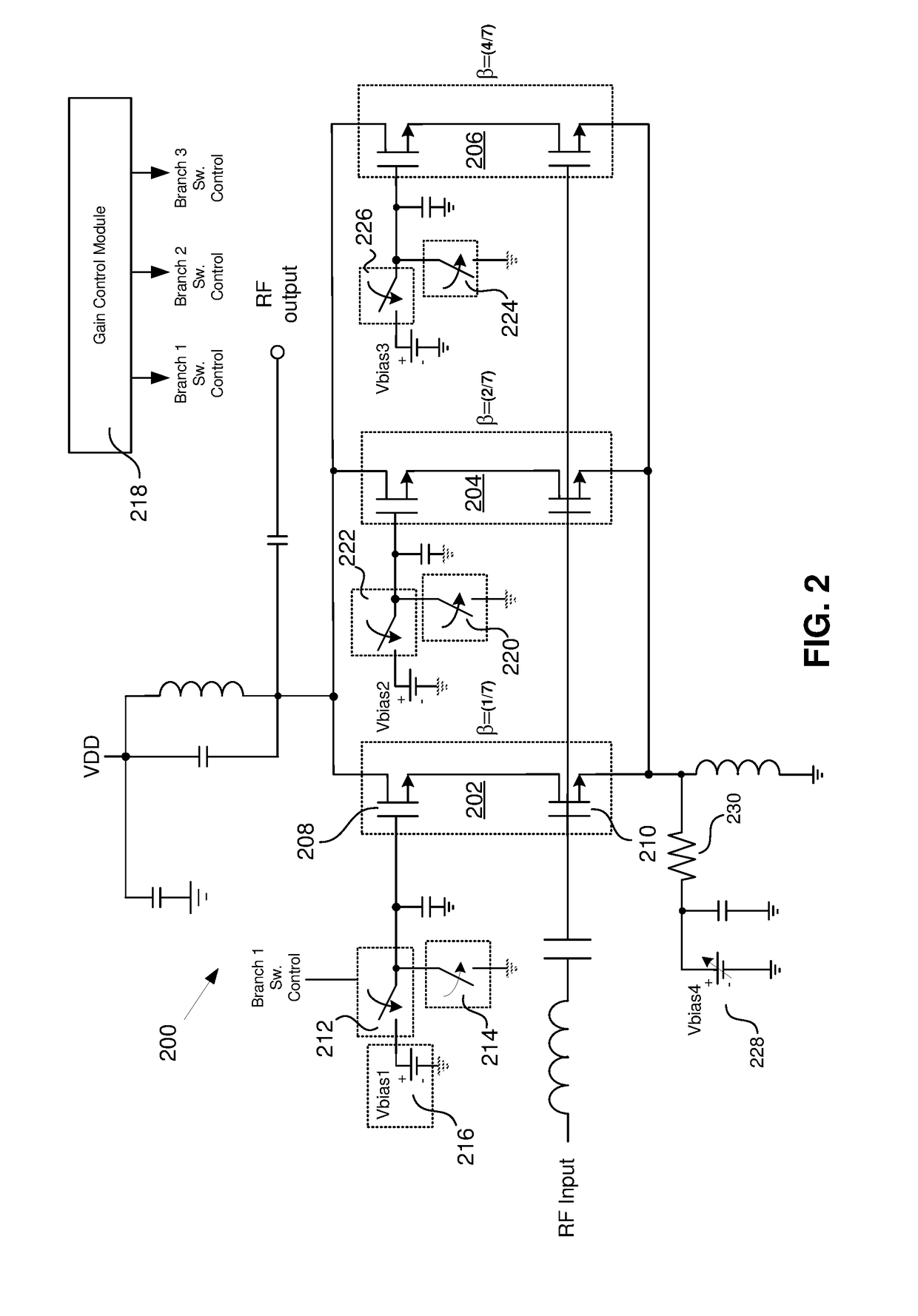
[0030]FIG. 2 is an illustration of an LNA 200 of one example of a communications receiver capable of operating in several gain modes. The LNA 200 comprises a plurality of amplifier branches 202, 204, 206, each branch having an amplifier. The inputs to each of the amplifier branches are coupled together. In some embodiments, a first FET 210 is configured as a common-source amplifier (i.e., “driver”) and a second FET 208 is configured as a common-gate amplifier (i.e., “cascode”). Alternatively, each amplifier branch can be configured as a single common source device or a stack of FET devices. In some embodiments, the branches include combinations of the above configurations. For the sake of simplicity, a cascode LNA is described in more detail below. However, it should be understood that the following description applies equally to other configurations of amplifier branches.

[0031]In some embodiments, each branch 202, 204, 206 has a “binary-weight”β. Accordingly, in some such embodimen...


PUM

PropertyMeasurementUnit
bias currentsaaaaaaaaaa

Abstract

A receiver front end capable of receiving and processing intraband non-contiguous carrier aggregate (CA) signals using multiple low noise amplifiers (LNAs) is disclosed herein. A cascode having a “common source” input stage and a “common gate” output stage can be turned on or off using the gate of the output stage. A first switch is provided that allows a connection to be either established or broken between the source terminal of the input stage of each cascode. Further switches used for switching degeneration inductors, gate / sources caps and gate to ground caps for each legs can be used to further improve the matching performance of the invention.

Description

BACKGROUND(1) Technical Field[0001]Various embodiments described herein relate to amplifiers, and more particularly, to low-noise amplifiers for use in communications equipment.(2) Background[0002]The front-end of a communications receiver typically includes an amplifier, such as a low-noise amplifier (“LNA”). The LNA is responsible for providing the first-stage amplification to a signal received by the communications receiver. The operational specifications of the LNA are very important to the overall quality of the communications receiver. Any noise or distortion introduced by the LNA will cause a degradation in the overall receiver performance. That is, the sensitivity of a receiver is in large part determined by the quality of the front-end, and in particular, by the quality of the LNA. The sensitivity of the receiver, in turn, determines the amount of information that can be transmitted in a predetermined amount of time (e.g., the bit rate in bits per second) at a predetermined...

Claims


Application Information

Patent Timeline
Patent Type & Authority Applications(United States)
IPC IPC(8): H03F1/32H03F1/56H03F3/195H03G3/00H03G3/10
CPCH03F1/3205H03F1/56H03F3/195H03G3/008H03G3/10H03G2201/307H03F2200/294H03F2200/387H03F2200/72H03F2200/75H03F2200/451H03F3/72H03G1/0029H03G1/0088H03G3/001H03F2200/18H03F2200/21H03F2200/211H03F2200/213H03F2200/222H03F2200/225H03F2200/24H03F2200/243H03F2200/249H03F2200/27H03F2200/297H03F2200/301H03F2200/306H03F2200/312H03F2200/391H03F2200/399H03F2200/417H03F2200/48H03F2200/489H03F2200/492H03F2200/495H03F2200/546H03G2201/106H03G2201/504H03G1/0094C03B5/193C03B5/2353C03B5/2356C03B7/02C03B37/022C03B37/07C03B37/075C03B37/0756C03B2201/00C03B2203/14C03B2203/16C03B2211/22C03B2211/23C03B2211/40C03B2211/60F23C6/047F23C2201/20F23C2201/301F23D14/22F23D14/62F23D14/78Y02P40/50
Inventor NOORI, HOSSEINCHENG, CHIH-CHIEH
Owner PSEMI CORP
Learn More