System and method for radar calibration using antenna leakage

Inactive Publication Date: 2006-10-12
UNITED STATES OF AMERICA THE AS REPRESENTED BY THE SEC OF THE ARMY
View PDF13 Cites 29 Cited by
  • Summary
  • Abstract
  • Description
  • Claims
  • Application Information

AI Technical Summary

Benefits of technology

[0006] The system and method for radar calibration using antenna leakage is a simplified means of calibrating the channels in amplitude and phase using natural signal leakage between antennas. It utilizes as a calibration signal a wideband sinusoidal Frequency Modulated Continuous Wave (FMCW) waveform with a modulation index and mo

Problems solved by technology

If such calibration is not performed, the amplitude and phase errors that are due to the channels themselves will falsely be attributed to the wave angle of the received beam and result in inaccuracies in the angular positional measurements of the target.
While this is adequate to perform the calibration, the injection circuitry takes up

Method used


Image

  • System and method for radar calibration using antenna leakage
  • System and method for radar calibration using antenna leakage
  • System and method for radar calibration using antenna leakage

Examples


Embodiment Construction

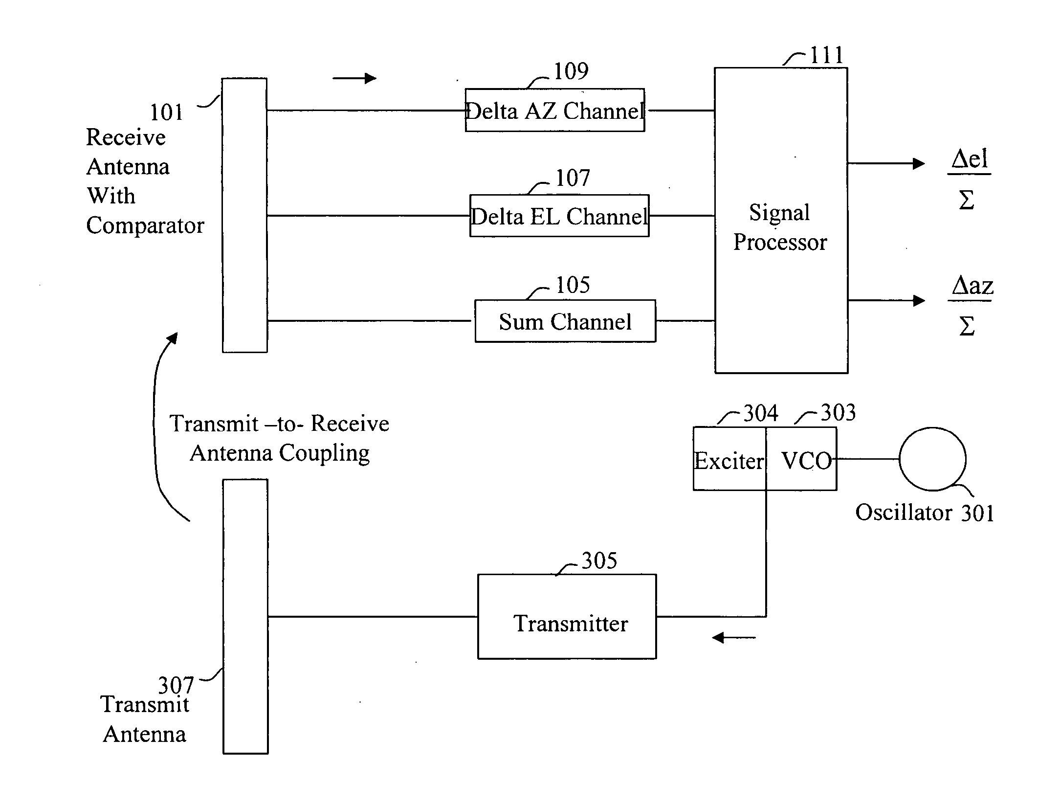
[0011] Referring now to the drawing wherein like numbers represent like parts in each of the several figures and lines with arrow heads indicate the direction of signal travel, the calibration scheme utilizing natural antenna leakage is explained in detail.

[0012] The calibration signal to be used is a wideband sinusoidal frequency modulated (FM) signal produced by applying a sinewave from low frequency oscillator 301 to the voltage output of high frequency voltage controlled oscillator (VCO). The sinusoidal frequency modulated signal can be described by the following equation:

S(t)=A*cos(2πfctΘ(t))

where Θ(t)=β*sin 2πfmt; fc=transmitting antenna frequency; fm=modulation frequency; A=amplitude of the signal; β, the modulation index, is defined as β=ΔF / fm; ΔF is the peak frequency deviation and t=time.

[0013] An exemplary spectrum is shown in FIG. 4 for a modulation index of 2.15. At each harmonic of the modulation frequency, there is a spectral line. For instance, if a 10 KHz modul...


PUM


Abstract

The system and method for radar calibration using antenna leakage is a simplified means of calibrating the channels in amplitude and phase using natural signal leakage between antennas. It utilizes as calibration signal a wideband sinusoidal Frequency Modulated Continuous Wave (FMCW) waveform with a modulation index and modulation frequency chosen to generate spectral components (or discrete signal frequencies) that fall within the receiver Doppler passband of the radar. The calibration signal is radiated out of the transmitting antenna and enters the radar receiver front-end through the transmit-to-receive antenna leakage which occurs naturally. This technique provides a low-complexity (simpler hardware realization) means for achieving a wideband calibration rapidly and is a practical alternative to the conventional calibration approach that relies on generating offset Doppler signals that are coupled into the radar receiver front-end through the use of couplers and cabling within the radar.

Description

DEDICATORY CLAUSE [0001] The invention described herein may be manufactured, used and licensed by or for the Government for governmental purposes without the payment to us of any royalties thereon.BACKGROUND OF THE INVENTION [0002] Radars generally employ monopulse direction-finding to determine the bearing angle to a selected target. In a typical monopulse direction-finding scheme, a single transmitted beam from a transmitting antenna (illuminator) radiates the target and is reflected by the target. From the reflected beam that is received at the receive antenna of the radar, four reference beams are generated; this may be the result of using one antenna for both the transmit and receive functions or a separate antenna exclusively for the receive function. [0003] From the four separate reference beams, the bearing angle to the target is derived in both the azimuth and elevation planes. This is illustrated in FIG. 1. As shown in the figure, the reference beams A, B, C and D from the...

Claims


Application Information

Patent Timeline
IPC IPC(8): G01S7/40
CPCG01S7/4026G01S13/44G01S2007/4069G01S2007/403G01S7/4056G01S2007/4034G01S7/403G01S7/4034G01S7/4069
Inventor CHRISTIAN, MICHAEL R.HALLADAY, RALPH H.
Owner UNITED STATES OF AMERICA THE AS REPRESENTED BY THE SEC OF THE ARMY
Why Eureka
Try Eureka