Apparatus and method for reducing induced drag on aircraft and other vehicles

a technology for aircraft and other vehicles, applied in the field of airfoils or watercraft structures, can solve the problems of increasing induced drag, reducing fuel economy and airspeed, and reducing airspeed, so as to reduce fuel consumption and airspeed. , the effect of reducing the weight of the wing structur

Inactive Publication Date: 2005-11-29
UTAH STATE UNIVERSITY
View PDF29 Cites 23 Cited by
  • Summary
  • Abstract
  • Description
  • Claims
  • Application Information

AI Technical Summary

Problems solved by technology

Conversely, when the angle of attack increases the wing produces more lift, therefore there is more induced drag.
As might be expected, induced drag is undesirable while flying in that it results in diminished fuel economy as well as decreased airspeed.
However, as the span is increased, the wing structural weight also increases and at some point the weight increase offsets the induced drag savings.
However, end plates are not employed widely due to their relative inefficiencies.
However, winglets cannot be used on all planes due to performance considerations which are not discussed here.
However, this reduction comes at a price.
This wingtip stall can lead to poor handling characteristics during stall recovery.
Unfortunately, there are several problems with elliptical wings.
First, elliptical shaped wings are cost prohibitive.
However, making an elliptical shape out of aluminum is quite difficult and therefore expensive.
Next, elliptical wings have undesirable stall characteristics.
An elliptical wing however, will tend to stall uniformly all along the span creating a potentially dangerous situation for the pilot.
When an aircraft may be increasing its angle of attack, i.e. increasing the lift of the wing, the airflow over the wing eventually reaches a point where it becomes turbulent, causing a loss in lift.
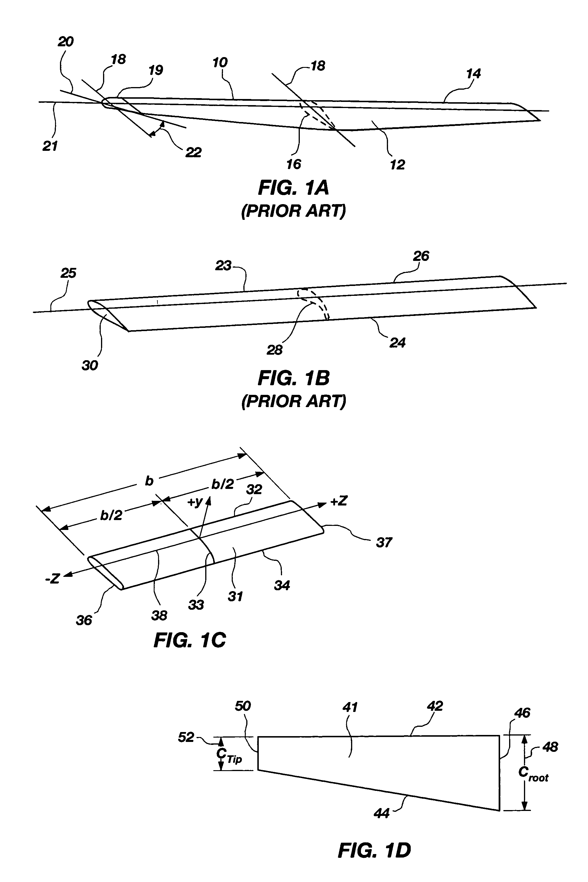
By twisting the front outboard portion of the wing down, the induced drag in that area may be decreased and the stall may be delayed in that area.
First, since the amount of twist may be integrated into a wing at the time of construction, usually for a design lift coefficient, the twist in a wing may only be optimized, if at all, for one portion of the expected flight envelope.
Second, washout comes at a price.
A wing with washout experiences a decrease in lift performance due to the reduction in the angle of attack.

Method used


Image

  • Apparatus and method for reducing induced drag on aircraft and other vehicles
  • Apparatus and method for reducing induced drag on aircraft and other vehicles
  • Apparatus and method for reducing induced drag on aircraft and other vehicles

Examples


Embodiment Construction

[0049]For the purposes of promoting an understanding of the principles in accordance with the disclosure, reference will now be made to the embodiments illustrated in the drawings and specific language will be used to describe the same. It will nevertheless be understood that no limitation of the scope of the disclosure is thereby intended. Any alterations and further modifications of the inventive features illustrated herein, and any additional applications of the principles of the disclosure as illustrated herein, which would normally occur to one skilled in the relevant art and having possession of this disclosure, are to be considered within the scope of the disclosure claimed.

[0050]The publications and other reference materials referred to herein to describe the background of the disclosure, and to provide additional detail regarding its practice, are hereby incorporated by reference herein in their entireties, with the following exception: In the event that any portion of said...


PUM


Abstract

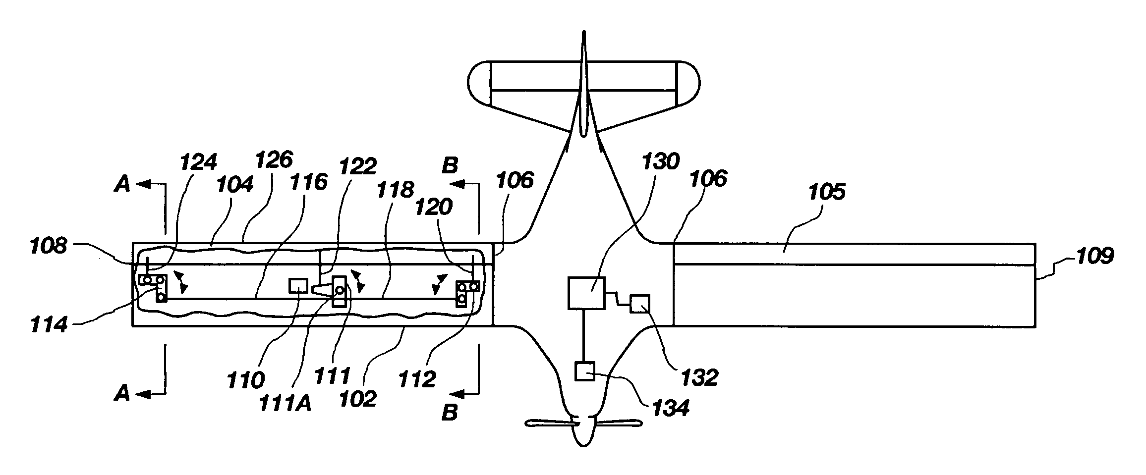
A method and apparatus for varying the washout of a wing such that induced drag is minimized during a flight. The washout is varied pursuant to an optimized twist distribution that depends on the wing planform and an optimized twist amount which depends, at least in part, upon the operating conditions, including those parameters used to determine the lift coefficient. The optimum twist may be employed by geometric or aerodynamic twist, including full spanwise control surfaces used to simultaneously provide roll control, high-lift and minimum induced drag. The optimum twist may also be employed be twisting just a portion of the wing or the entire wing, either geometrically or aerodynamically.

Description

CROSS-REFERENCE TO RELATED APPLICATIONS[0001]This application is a continuation of co-pending U.S. patent application Ser. No. 10 / 799,568, filed Mar. 11, 2004, entitled “APPARATUS AND METHOD FOR REDUCING INDUCED DRAG ON AIRCRAFT AND OTHER VEHICLES.” This application also claims the benefit of U.S. Provisional Application Ser. No. 60 / 552,252, filed on Mar. 10, 2004, now abandoned, entitled APPARATUS AND METHOD FOR REDUCING INDUCED DRAG ON AIRCRAFT. Both of the afore-mentioned applications are hereby incorporated by reference herein in their entireties, including but not limited to those portions that specifically appear hereinafter, the incorporation by reference being made with the following exception: In the event that any portion of the above-referenced applications is inconsistent with this application, this application supercedes said above-referenced applications.STATEMENT REGARDING FEDERALLY SPONSORED RESEARCH OR DEVELOPMENT[0002]Not Applicable.BACKGROUND[0003]1. The Field of ...

Claims


Application Information

Patent Timeline
Patent Type & Authority Patents(United States)
IPC IPC(8): B64C1/00B64C3/10B64C3/14B64C3/48B64C3/52G05D1/00
CPCB64C3/10B64C3/14B64C3/48B64C3/52Y02T50/12Y02T50/145Y02T50/10
Inventor PHILLIPS, WARREN F.
Owner UTAH STATE UNIVERSITY
Why Eureka
Try Eureka