Adjustable compression ratio apparatus

Inactive Publication Date: 2005-12-06
GRABBE WALLACE W
View PDF21 Cites 11 Cited by
  • Summary
  • Abstract
  • Description
  • Claims
  • Application Information

AI Technical Summary

Benefits of technology

[0003]When the firing chamber is made smaller in order to increase the compression ratio when the engine power is less than full, it increases the number of times the energy giving gasses are allowed to expand in the power stroke and therefore also adds to the engine efficiency.
[0009]More particularly, the apparatus further includes a control shaft actuator connected to the control shaft by an actuator arm and a throttle linkage. In this manner, movement of the throttle linkage effects operation of the apparatus and ultimate control of the compression ratio.

Problems solved by technology

The gasoline engine is inefficient because it has a high compression only when it is at “full throttle”, at a time when wind resistance is at its peak, and the carburetor is receiving an extra rich mixture of fuel to avoid burning the engine.
It is evident that most inventors don't account for the extreme forces they are dealing with in the crank case.
Another negative in correcting this shortcoming seems to be the necessity of adding so much gadgetry to such a simple machine.
This becomes a small objection when considering the recent changes in the availability of fuel today.

Method used


Image

  • Adjustable compression ratio apparatus
  • Adjustable compression ratio apparatus
  • Adjustable compression ratio apparatus

Examples


Embodiment Construction

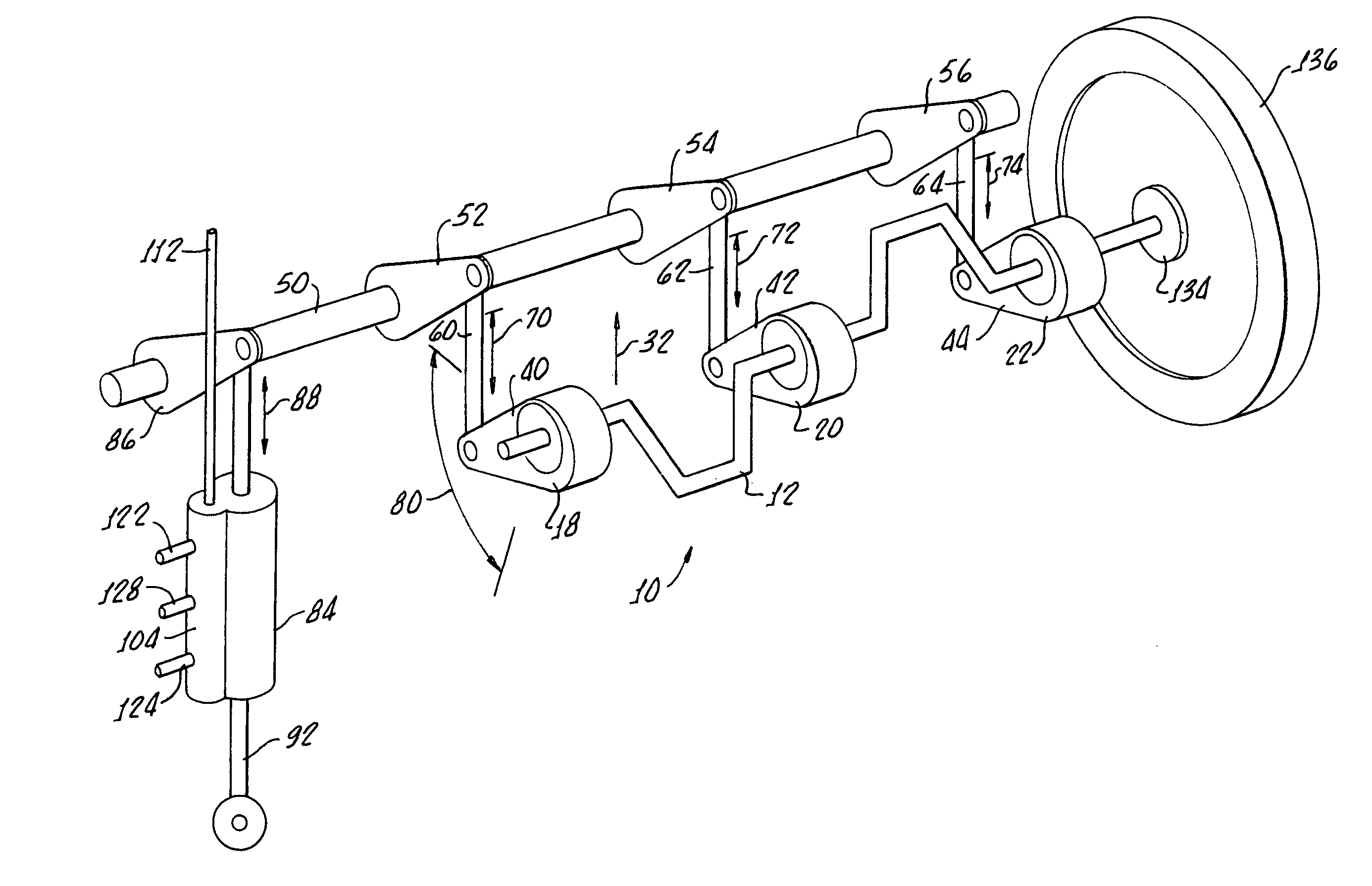
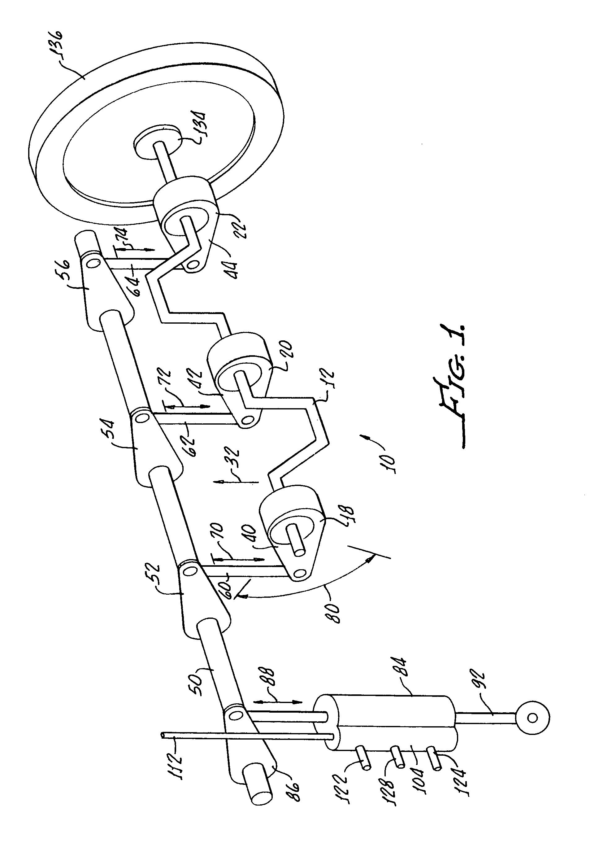
[0018]With reference to FIG. 1, there is diagramed apparatus 10 in accordance with the present invention for adjusting a compression ratio of an engine (not shown) having a crankshaft 12. The engine includes a plurality of combustion cylinders, a moveable piston disposed within each of the combustion cylinders, and rods connecting each piston to the crankshaft 12, these elements, not being claimed are omitted from the drawings for the sake of clarity.

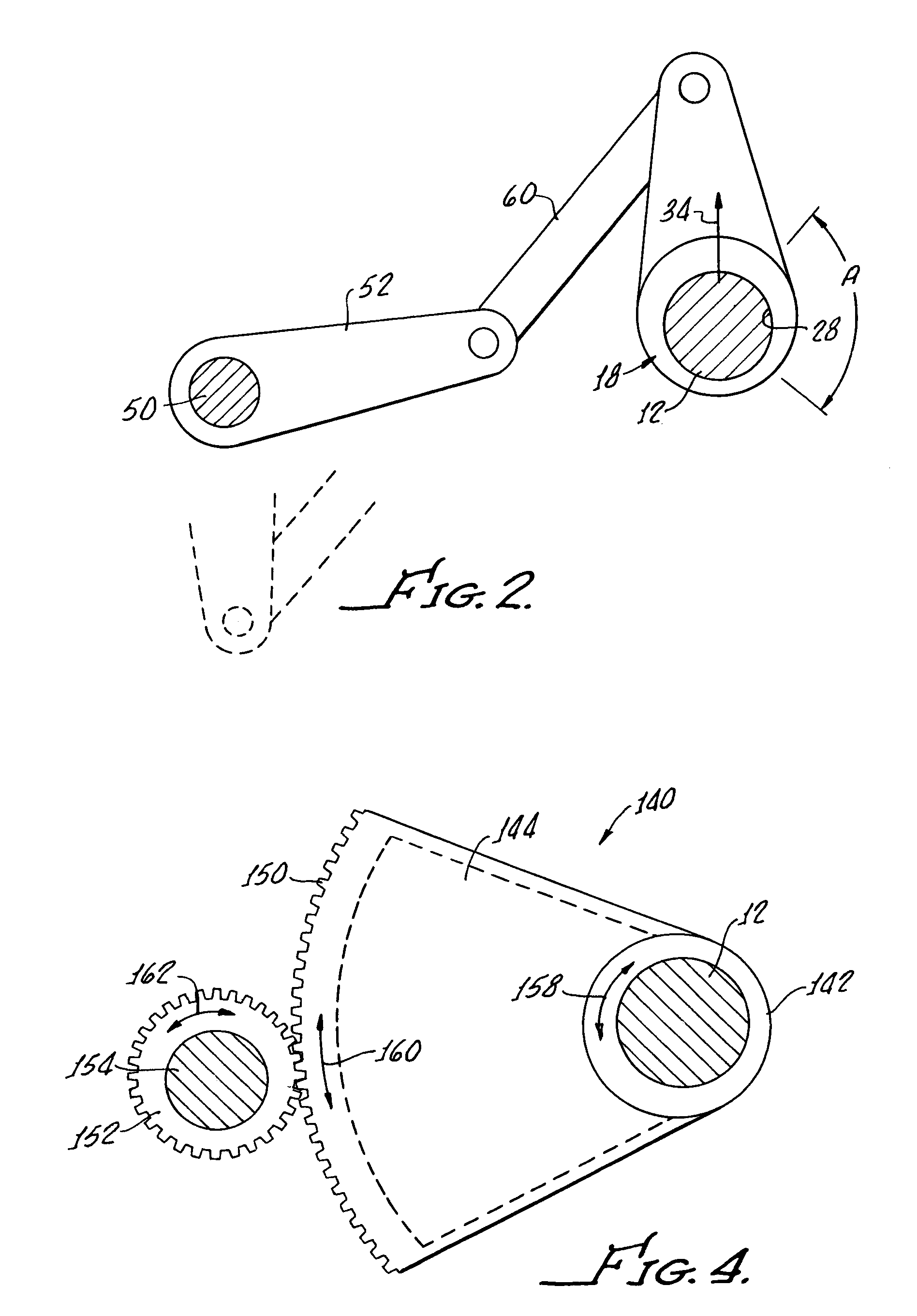
[0019]The apparatus 10 includes a plurality of bearings 18, 20, 22, surrounding the crankshaft 12 at every main bearing of the engine. As shown in FIG. 2 bearing 18 includes an offset bore therethrough for supporting a crankshaft 12, only one bearing 18 being shown for the sake of clarity.

[0020]It should be apparent that angular displacement as indicated by the arrows A in FIG. 2 causes off axis displacement of the crankshaft 12 as illustrated by the arrow 32 in FIG. 1. As shown a 90° rotation of the bearing 18 equals approximately a 5 / ...


PUM


Abstract

Apparatus is provided for adjusting a compression ratio of an engine having a crankshaft, a plurality of combustion cylinders, a moveable piston disposed within each combustion cylinder, and rods connecting each piston of the crankshaft. The apparatus generally includes a plurality of bearings surrounding a crankshaft at each main bearing with each bearing having an offset bore therethrough supporting the crankshaft. Rotational displacement of the bearings causes off axis displacement of the crankshaft along the longitudinal axes of the rods, thus raising and lowering the scope of movement of each piston and thereby increasing and decreasing the compression ratio without changing piston stroke. Rotational displacement of the bearings may be provided through an actuator interconnected to a throttle linkage.

Description

[0001]The present invention is generally related to improvements in internal combustion engines having reciprocating pistons and is more particularly directed to apparatus for varying the cylinder compression ratio during operation in order to optimize the efficiency of the engine.[0002]The gasoline engine is inefficient because it has a high compression only when it is at “full throttle”, at a time when wind resistance is at its peak, and the carburetor is receiving an extra rich mixture of fuel to avoid burning the engine. And engines today are designed “square” (piston diameter is about equal to the stroke). It is necessary in order to get good performance at high speed. A longer stroke would get more energy from the fuel.[0003]When the firing chamber is made smaller in order to increase the compression ratio when the engine power is less than full, it increases the number of times the energy giving gasses are allowed to expand in the power stroke and therefore also adds to the e...

Claims


Application Information

Patent Timeline
IPC IPC(8): F02B75/04
CPCF02B75/047
Inventor GRABBE, WALLACE W.
Owner GRABBE WALLACE W
Why Eureka
Try Eureka