Backflow prevention valve
a backflow prevention and valve body technology, applied in functional valve types, liquid fuel feeders, machines/engines, etc., can solve the problems of unstable movement the inability of the valve member e to move smoothly, and achieve reliably close, reliable and stable opening and closing movement
- Summary
- Abstract
- Description
- Claims
- Application Information
AI Technical Summary
Benefits of technology
Problems solved by technology
Method used
Image
Examples
first embodiment
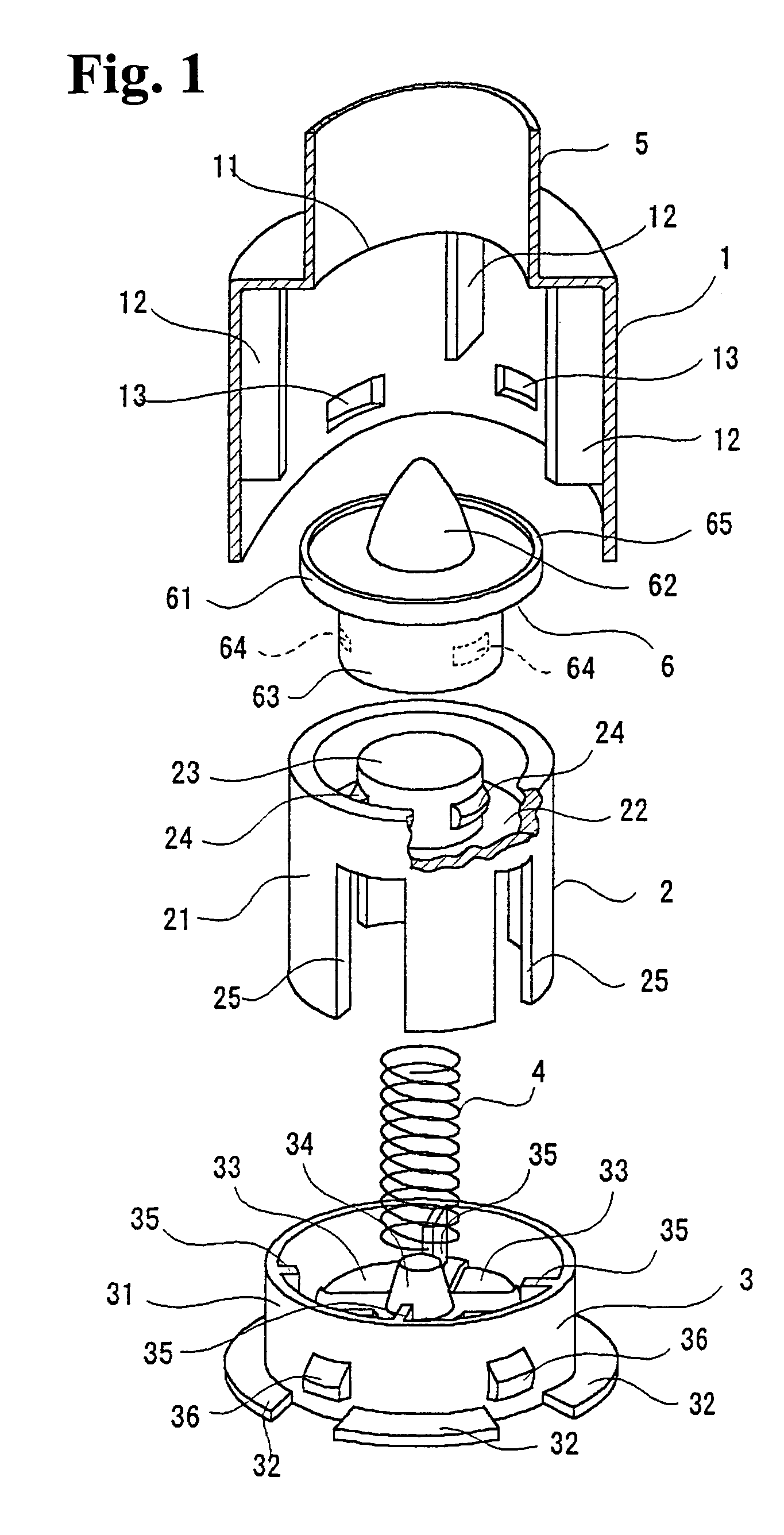
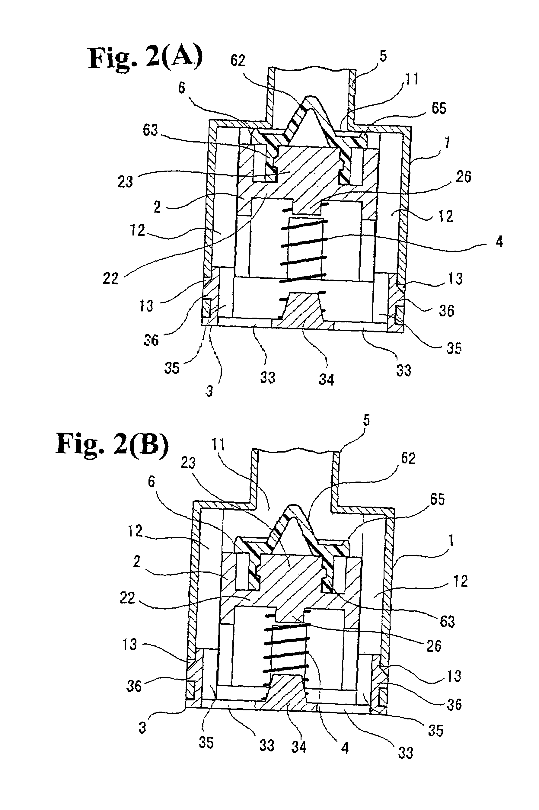
[0026]FIGS. 1 and 2(A), 2(B) show a backflow prevention valve according to the present invention. As shown in FIG. 1, the backflow prevention valve includes a cylindrical case member 1; a valve member 2 disposed inside the case main member 1 to be movable along an axial direction; a coil spring (urging device) 4 for urging the valve member 2; and a covering member 3 for closing a lower end of the case member 1.
[0027]A ring-shape wall plate is provided at an upper end of the case member 1, and a circular inflow opening 11 is provided at a center of the wall plate. A liquid inflow pipe 5 with a smaller diameter than that of the case member 1 is integrally connected to the inflow opening 11 from outside. Four ribs 12 (only three are shown in FIG. 1) are projected on an inner peripheral surface of the case member 1 along the axial direction at positions shifted by 90 degrees with each other. Furthermore, four engagement holes 13 (only two are shown in FIG. 1) are formed at a lower end o...
second embodiment
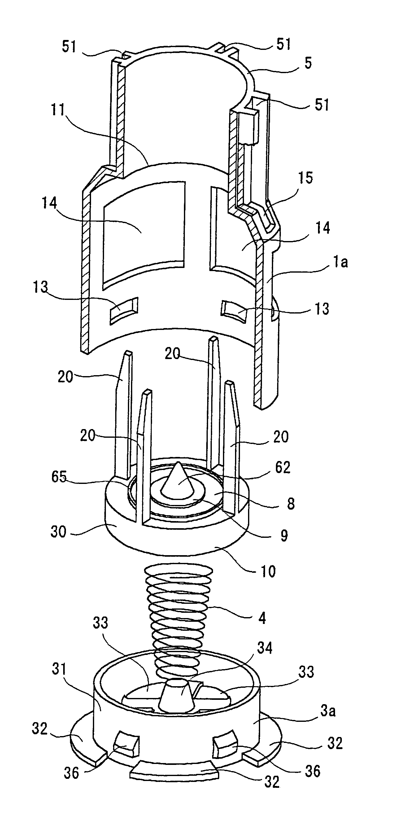
[0046]As shown in FIGS. 5(A) and 5(B), the valve member 10 is formed of a cylindrical main member 30 with an upper wall. Four guiding arms 20 are provided at a peripheral edge of an upper surface of the main member 30 at positions shifted by 90 degrees with each other. The cap member 9 and the sealing member 8 are fixed to the top surface of the main member 30 similar to the
[0047]As shown in FIGS. 6(A) and 6(B), the valve member 10 is housed to be movable inside the case member 1a in a state that each guiding arm 20 is projected outside through each hole 15. Each four guiding arm 20 projecting from the case member 1a is inserted and capable of sliding in each guiding slot 51 formed on the outer peripheral surface of the liquid inflow pipe 5.
[0048]In the backflow prevention valve, as shown in FIGS. 6(A) and 6(B), the guiding arms 20 slide inside the guiding slots 51 to support and guide the valve member 10, so that the opening and closing movements of the valve member 10 can be carri...
third embodiment
[0050]In the backflow prevention valve of the third embodiment, the guiding arms 20 are inserted and capable of sliding in the guiding slots 51 through the holes 15 to support and guide the valve member 10. Alternatively, the holes 15 are formed in approximately the same sectional shape and size as the guiding arms 20, and the guiding arms slide inside the holes 15, thereby supporting and guiding the opening and closing movements of the valve member 10. In this case, the guiding slots 51 can be omitted. Further, it is possible to configure that the holes 15 and guiding slots 51 support and guide the opening and closing movements of the valve member 10 without omitting the guiding slots 51.
[0051]As described above, in the backflow prevention valves in the first, second, and third embodiments according to the present invention, the inner peripheral surface of the liquid inflow pipe 5 has a smooth surface without unevenness. As shown in the first and second embodiments, the supporting ...
PUM
 Abstract
Description
Claims
Application Information
 - R&D
- Intellectual Property
- Life Sciences
- Materials
- Tech Scout
- Unparalleled Data Quality
- Higher Quality Content
- 60% Fewer Hallucinations
Browse by: Latest US Patents, China's latest patents, Technical Efficacy Thesaurus, Application Domain, Technology Topic, Popular Technical Reports.
© 2025 PatSnap. All rights reserved.Legal|Privacy policy|Modern Slavery Act Transparency Statement|Sitemap|About US| Contact US: help@patsnap.com


