

Piezoelectric actuator
a technology of actuators and piezoelectric plates, applied in printing and other directions, can solve the problems of poor energy efficiency of piezoelectric plates, and achieve the effect of sufficiently deforming the piezoelectric plate and high energy efficiency
- Summary
- Abstract
- Description
- Claims
- Application Information
AI Technical Summary
Benefits of technology
Problems solved by technology
Method used
Image

Examples
first embodiment
[0048]First, an ink jet head 100, which serves as an example of a liquid transport device provided with a piezoelectric actuator according to the present invention, will be described while referring to FIGS. 2 to 11.
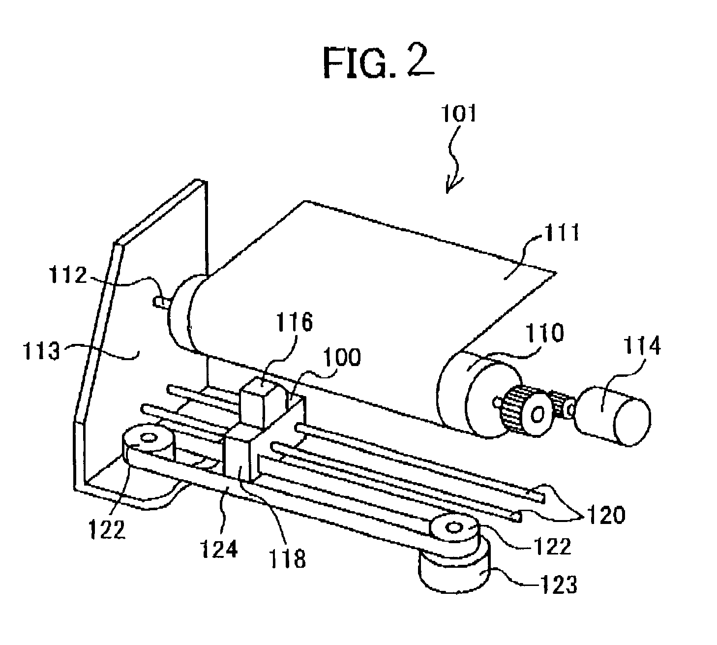
[0049]First, an ink jet printer 101 mounted with the ink jet head 100 will be described while referring to FIG. 2.
[0050]As shown in FIG. 2, the ink jet printer 101 includes a platen roller 110 and a carriage 118. The platen roller 110 is rotatably attached to a frame 113 by a shaft 112 and is driven to rotate by a motor 114 to transport sheets 111 one at a time past the carriage 118. The carriage 118 is slidably mounted on two guide rods 120, which are oriented in parallel with the rotational axis of the platen roller 110. The carriage 118 is coupled to a timing belt 124, which is provided around a pair of pulleys 122. A motor 123 is provided for driving one of the pulleys 122 in both forward and in reverse directions. The carriage 118 supports the ink jet head 100 and a...
second embodiment
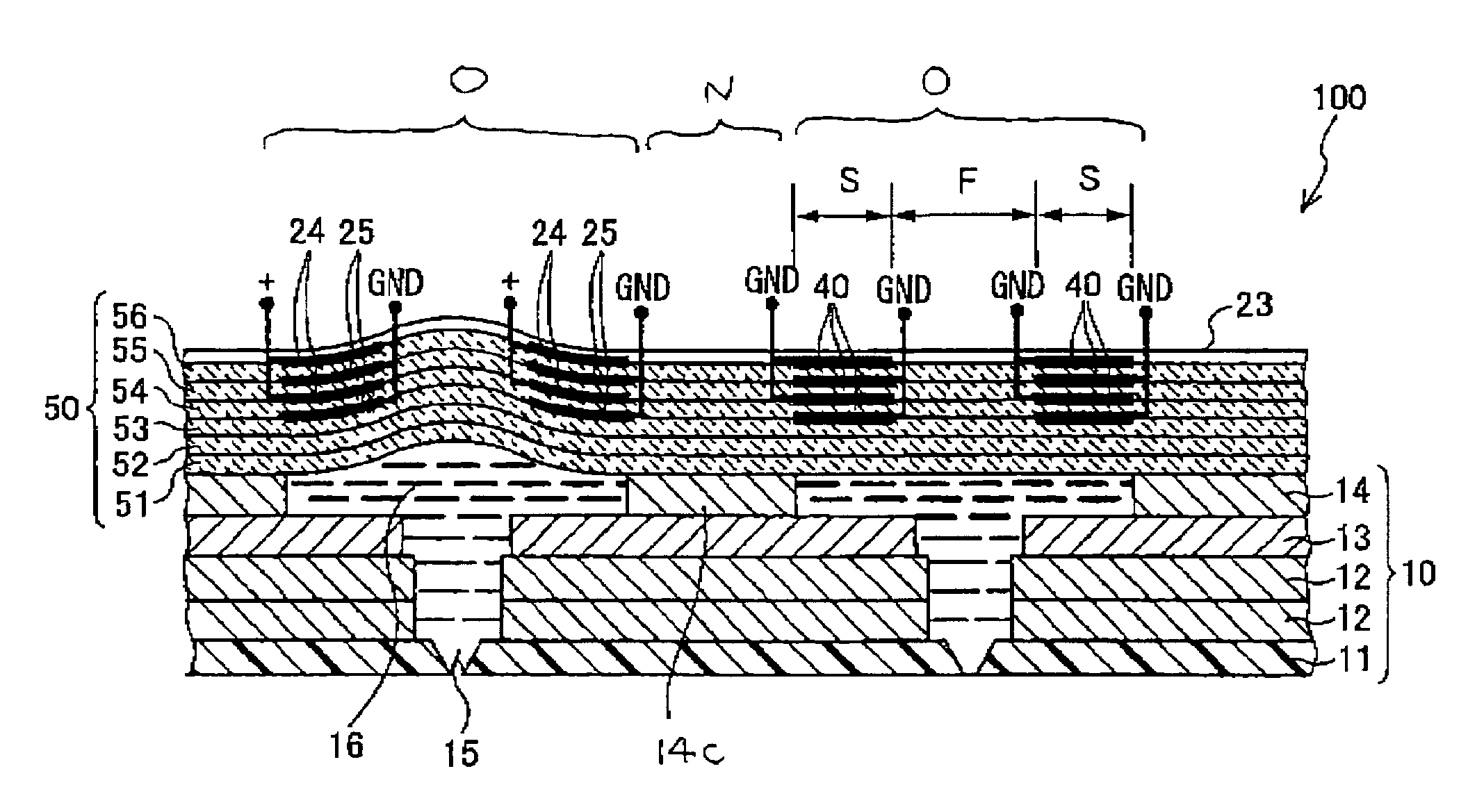
[0092]Next, an ink jet head 100 including a piezoelectric actuator 50 according to the invention will be described while referring to FIG. 13(A).
[0093]It should be noted that the ink jet head 100 includes a cavity plate 10 with the same configuration as the cavity plate 10 of the first embodiment.
[0094]In the same manner as in the first embodiment, the piezoelectric actuator 50 has an operation portion O for every pressure chamber 16, and has a first portion F and a pair of second portions in each operation portion O.
[0095]In the present embodiment, in the second portions S, the electrodes 24, 25 are provided on the upper sides of the piezoelectric sheets 51–53 that are located close to the pressure chambers 26 in the thickness direction of the piezoelectric actuator 50. Accordingly, the electrodes 24 and 25 are disposed between adjacent layers of the piezoelectric sheets 51–54 in the direction in which the piezoelectric sheets are stacked.
[0096]In the first embodiment, each electro...
third embodiment
[0113]Next, an ink jet head 100 including a piezoelectric actuator 50 according to the present invention will be described with reference to FIG. 14.
[0114]The piezoelectric actuator 50 of the present embodiment has a configuration similar to the piezoelectric actuator 50 of the first embodiment. However, a notch 57 is formed in the surface of the first portion F that is opposite from the surface adjacent to the pressure chamber 16. Said differently, the notch 57 is formed in the surface of the first portion F at a position shifted in the thickness direction of the piezoelectric actuator 50 in the direction in which the first portion F archingly protrudes. In this example, the notch 57 is formed by removing the portion of the piezoelectric sheets 54–56 in the first portion F.
[0115]A connection electrode 58 is formed, for example by deposition of a conductive material, on the inner surface of the notch 57 and on the top surface 50a of the piezoelectric actuator 50. Wiring that extends...
PUM
 Abstract
Description
Claims
Application Information