
Device and method for measuring absorbed heat flux in a fire test apparatus

a technology of absorbing heat flux and fire test apparatus, which is applied in the direction of heat measurement, material flaw investigation, instruments, etc., can solve the problems of no standard device or method for measuring the heat flux actually absorbed by specimens in fire test apparatus, and the incident of all the heat flux on the coating is absorbed, etc., to overcome possible measurement errors, measure rather accurately, and be convenient, accurate and reliable

Inactive Publication Date: 2005-12-06
FACTORY MUTUAL INSURANCE COMPANY
View PDF9 Cites 7 Cited by
  • Summary
  • Abstract
  • Description
  • Claims
  • Application Information

AI Technical Summary

Benefits of technology

[0006]It is quite convenient to measure electrical power as a substitute for measuring a radiant flux. Electrical power can be measured rather accurately. The advantage of using ESR is that it overcomes possible measurement errors due to heat losses from the surface, (e.g. convection, surface radiation, conduction, etc). By reproducing the temperature rise, one insures that the heat losses are the same for both the imposed radiant flux, Φ, and electrical power per unit area, P. Indeed, the technique provides a convenient, accurate and reliable method for calibrating the radiant heaters of the fire test apparatus. It is an absolute (i.e. primary) method of calibration of the radiant heaters irradiating a specimen having a defined surface coating. It depends solely on one's ability to measure the electrical power P that reproduces the measured temperature rise.
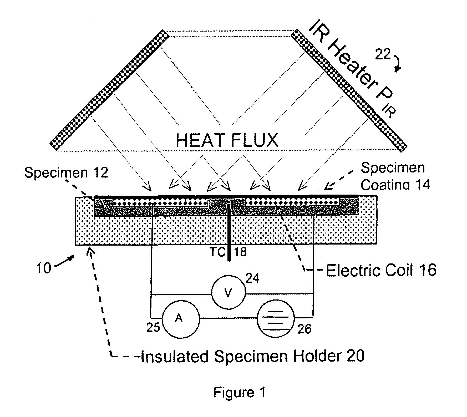
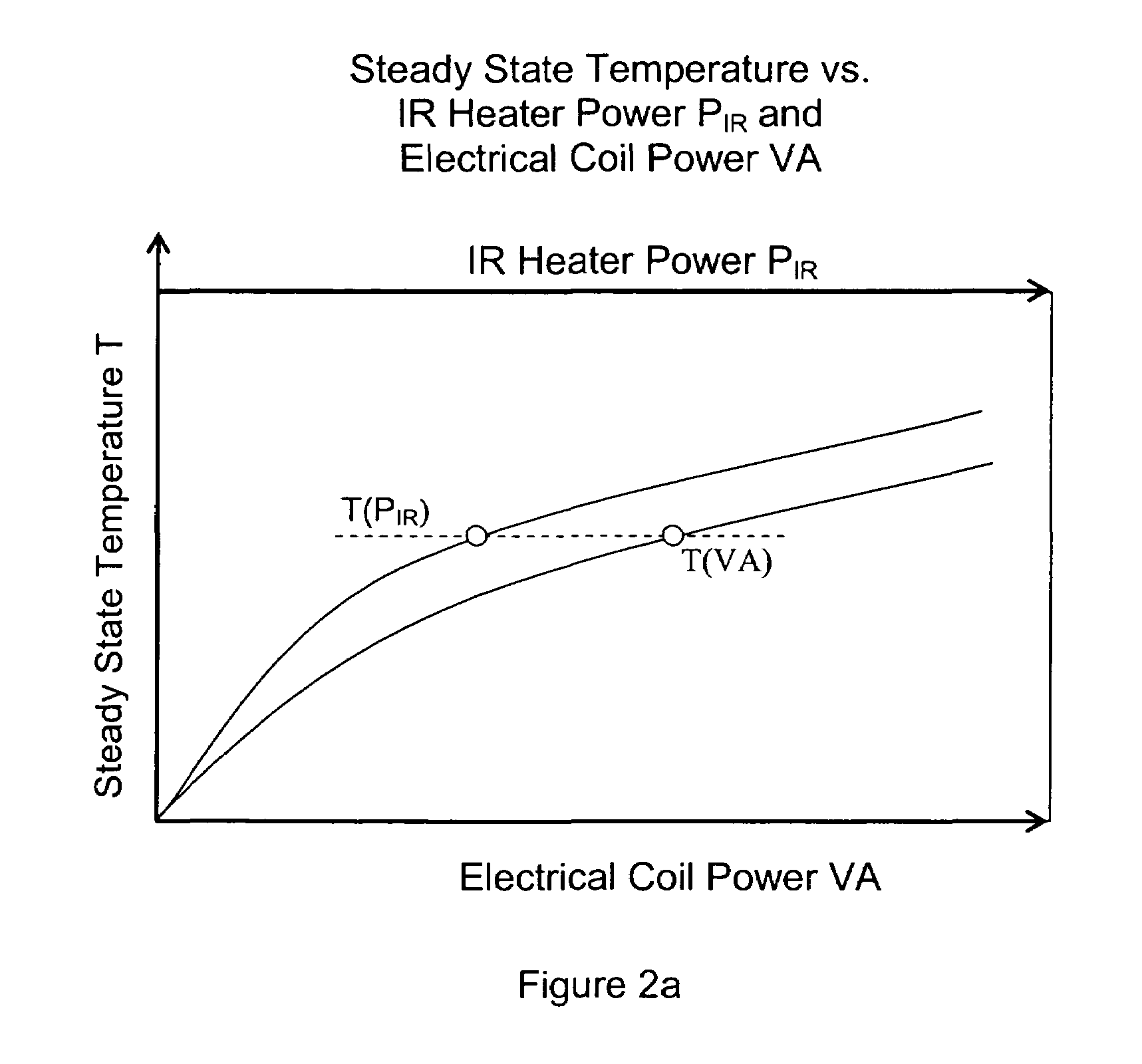
[0007]In accordance with the present invention, the principle of ESR is applied to the device in connection with testing of specimen materials or objects to determine the heat flux involved in causing the specimen to ignite, become inoperative, begin to vaporize or exhibit some other characteristic in response. More specifically, for low heat fluxes, the coated disk is exposed to a heat flux from a radiant heat source, such as an IR heating apparatus, until the thermocouple records a steady-state temperature, where the heat absorbed by the disk is equal to the heat losses given off by the disk. Subsequently, with no incident radiant heat flux on the coated disk, the IR heating is reduced to zero, and an electrical power of sufficient magnitude is supplied to the imbedded electrical heating coil for the disk to return to the same steady-state temperature. Electrical power used by the electrical heating coil to return the disk to the same steady-state temperature is equal to the total heat absorbed by the disk in the IR heating apparatus. The electrical power can be accurately measured. In a test apparatus in which the angle of incidence is set, the specimen, which has the same coating as the disk, as well as the same coated surface area and same insulation as the disk, receives the same heat flux as the disk. This application of absolute electrical substitution radiometry (ESR) can be performed for various levels of incident flux, supplied electrical power supply, and steady-state disk temperature.

Problems solved by technology

However, because of the coating, not all of the heat flux incident on the coating is absorbed by the specimen, and the portion of the heat flux emanating from radiant heating source that is absorbed by the specimen varies from one coating to another.
As a result, there is a problem evaluating and comparing test data from specimens having different coatings.
However, prior to the present invention, there was no standard device or method for measuring the heat flux actually absorbed by a specimen in a fire test apparatus.

Method used


Image

  • Device and method for measuring absorbed heat flux in a fire test apparatus
  • Device and method for measuring absorbed heat flux in a fire test apparatus
  • Device and method for measuring absorbed heat flux in a fire test apparatus

Examples


Embodiment Construction

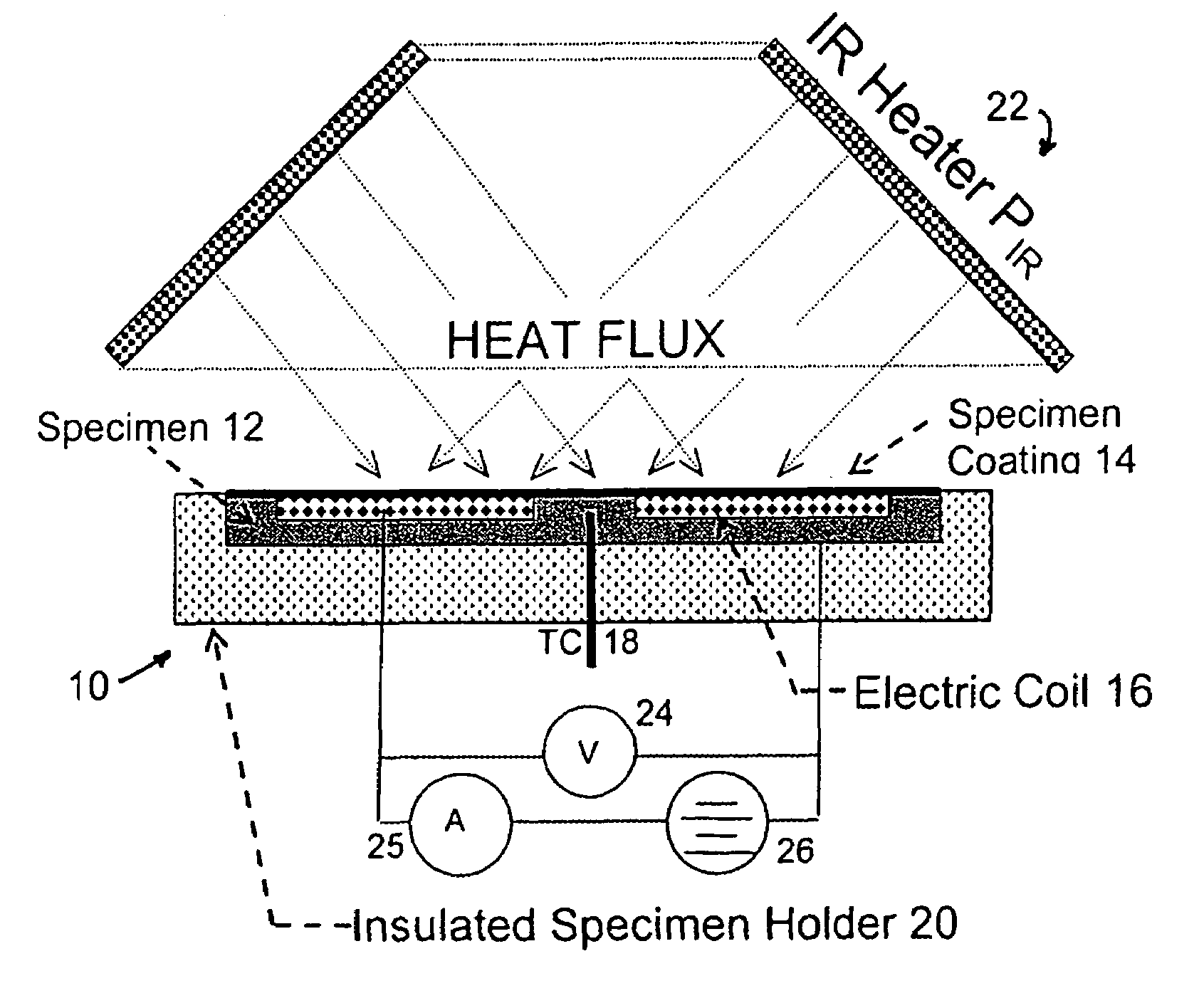
[0015]As can be seen from FIG. 1, a device for determining the radiant heat flux received by a test specimen having a coating to improve the absorption of the radiant heat flux, which is designated generally by the reference numeral 10, has a body 12, and a coating 14 on the body, the coating on the body being the same as the coating on the test specimen. The device 10 also has an electrical heating element 16 in heat transfer relationship with the body 12, such that the coating 14 is not interposed between the heating element and the body. A thermal detector, such as a thermocouple 18 connected to the body 12, for indicating the temperature of the body is also a part of the device 10. The body 12 is a metal disk of, for example, copper, and the electrical heating element can be an electric resistance heating element and can be positioned within the body.

[0016]The device 10 further includes an insulated holder 20 for the body 12, wherein the body has a first surface to which the coa...


PUM

PropertyMeasurementUnit
radiant heat fluxaaaaaaaaaa
areaaaaaaaaaaa
heat transferaaaaaaaaaa

Abstract

A device for measuring the flux received by a specimen in fire test apparatuses has a copper disk or plate of the same dimensions and the same type of surface coating as a typical material specimen, an embedded heating coil and thermocouple, and an insulated sample holder similar to that used for a specimen. The transient response of the embedded thermocouple is measured for several different levels of imposed incident radiation without electrical heating and for several different known levels of electrical heating without any imposed radiation. The principle of Electrical Substitution Radiometry (ESR) is applied, and the transient responses to incident radiation and electrical heating under identical thermal conditions are compared to determine the amount of incident radiation that is actually absorbed by the device while it is being irradiated. The situations are kept thermally identical, thereby insuring that all effects due to heat losses (e.g. convection, radiation and conduction) are exactly the same.

Description

BACKGROUND OF THE INVENTION[0001]Test apparatuses approved by ASTM International, Inc. for measuring the fire hazard of materials or objects, such as the Cone Calorimeter and the Fire Propagation Apparatus, irradiate a specimen of a material or an object with a known infrared (IR) heat flux from a radiant heating source. The specimen is typically coated with paint or a carbon mixture to improve absorption of the radiant heat flux in order to simulate heat absorption during an actual fire, when the material or object becomes covered with soot and thereby absorbs most of the radiant energy incident upon it. The purpose of the test is to determine, for example, when the specimen material or object, such as an electrical component, ignites, becomes inoperative or begins to vaporize. The fire test apparatuses employ radiant heaters to simulate the heating by a fire.[0002]The incident heat flux from the radiant heater is often taken as a measure of the heat flux required to cause the dete...

Claims


Application Information

Patent Timeline
Patent Type & Authority Patents(United States)
IPC IPC(8): G01N25/18G01N25/50
CPCG01N25/18G01N25/50
Inventor DE RIS, JOHN L.KHAN, MOHAMMED M.
Owner FACTORY MUTUAL INSURANCE COMPANY
Learn More