Rotatable connector for a battery cable clamp

a battery cable clamp and rotatable technology, which is applied in the direction of electrical connections, electrical connection structural associations, connections, etc., can solve the problems of reducing the electrical power available, affecting the corrosion of the battery post to attach by corrosion, so as to achieve the effect of reducing easy to loosen, and increasing the clamping pressure of the bol

Inactive Publication Date: 2005-12-06
FENELON MARGARET FENE +1
View PDF18 Cites 36 Cited by
  • Summary
  • Abstract
  • Description
  • Claims
  • Application Information

AI Technical Summary

Benefits of technology

[0005]Instead of the standard bolt which passes through the ends of the yoke and nut that is tightened to secure the clamp about the battery post, the battery cable clamp of the invention utilizes a bolt with a clamping handle. The connection between the bolt head and the attached handle includes a boss or camming structure that increases or decreases the clamping pressure of the bolt based on a small rotation of the handle. Thus, the nut on the bolt connecting the two legs of the yoke can be tightened finger tight and the handle rotated approximately half of a turn to substantially increase the clamping pressure of the bolt. When it is desired to remove the battery cable clamp, the handle can be released and a substantial decrease in the clamping pressure of the bolt results. The nut on the bolt can then be easily loosened to relieve additional pressure on the battery cable clamp. The handle may be rotated into an upper locking and unlocking position, and downward to lay upon the surface of the battery. Preferably at least the handle, nut and seat interfacing with the boss on the handle are made of non-corrosive and even non-metallic materials. In this fashion, preferably the entire operation of the invention is possible without the need for using any additional tools.

Problems solved by technology

During the course of the life of a battery, corrosion buildup may occur and may cause the battery clamp to attach by corrosion to the battery post.
Corrosion also tends to build up between the bolt and the nut threaded on the bolt and used to tighten the yoke about the battery post.
Corrosion may impair the proper transmission of battery power from the battery post through the battery cable clamp to the battery cable thereby diminishing the electrical power available.
Because of the corrosion of the nut to the bolt clamping the yoke to the battery post, either the process of cleaning the battery post and battery cable clamp or replacing the battery can be time consuming and difficult.

Method used


Image

  • Rotatable connector for a battery cable clamp
  • Rotatable connector for a battery cable clamp
  • Rotatable connector for a battery cable clamp

Examples


Embodiment Construction

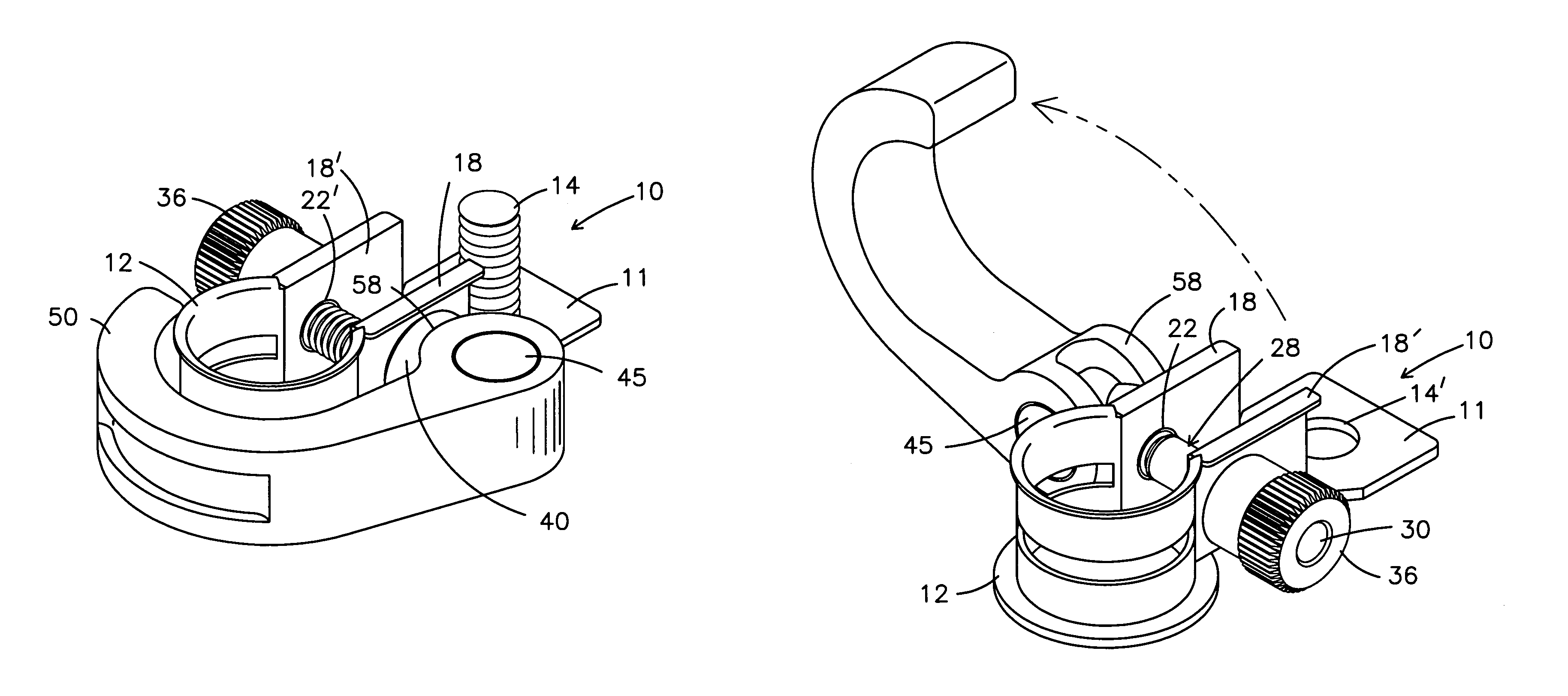
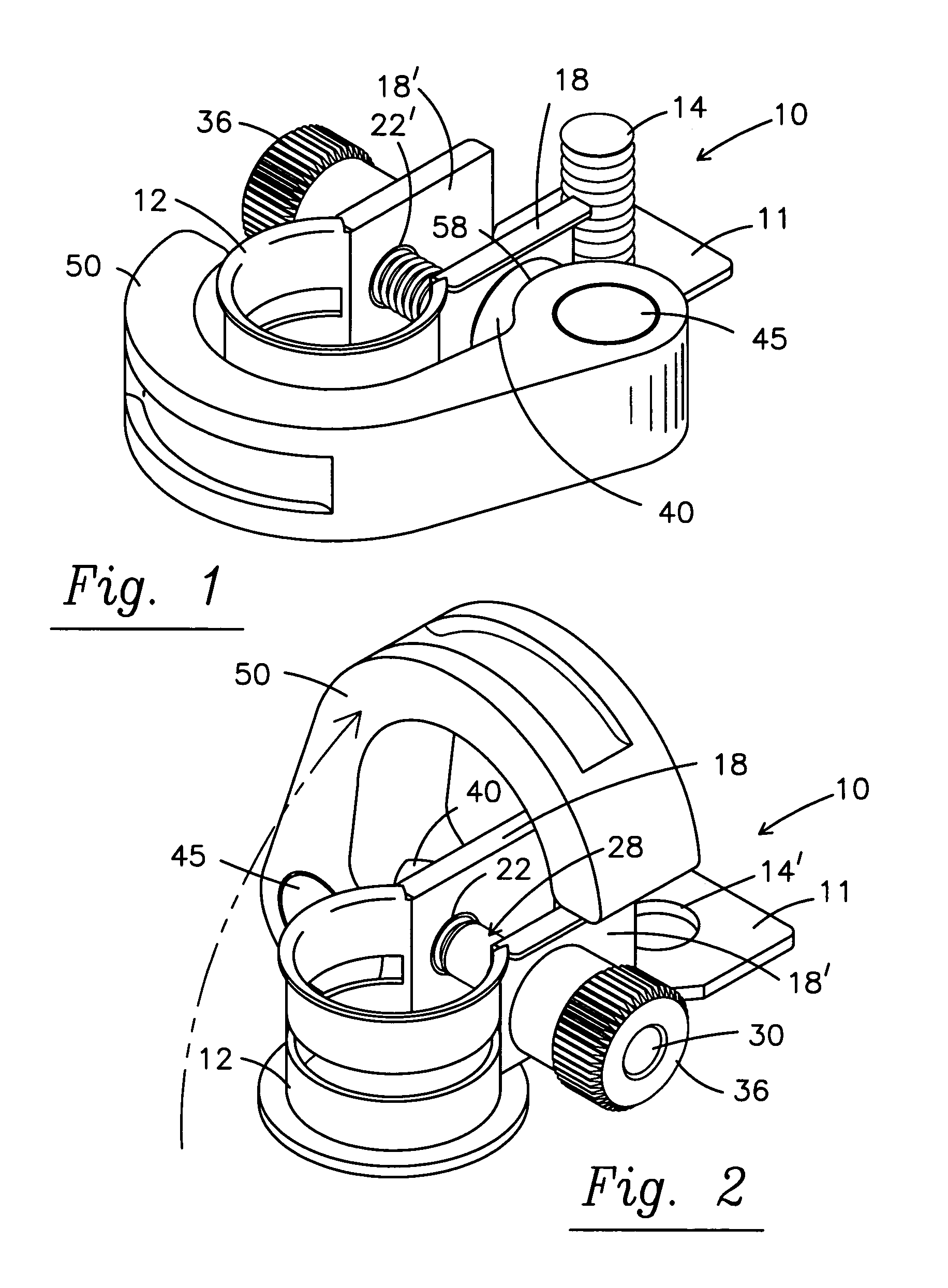
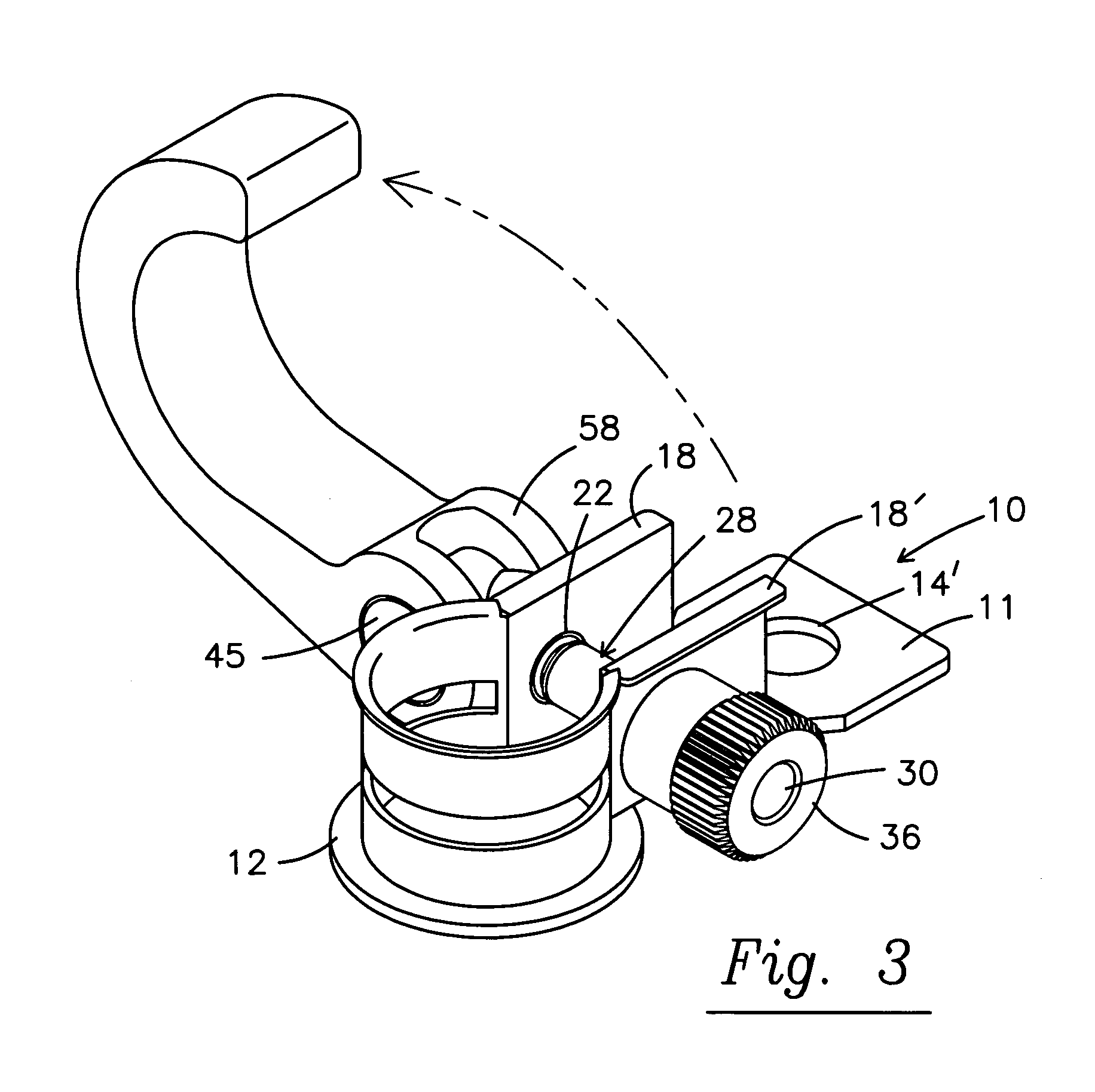
[0024]A description of the preferred embodiment of the present invention will be best understood by referring to FIGS. 1–9 of the accompanying drawings wherein like reference numerals refer to like parts.

[0025]Referring first to FIG. 9a, prior art steel battery clamp 110 is shown having a first end with crimping section 111 to connect with battery cable C and post section 112 encompassing the battery terminal T and legs 118, 118′ extending from each side of the post section of the yoke and having apertures therein to receive a bolt B that is tighten nut N to securely clamp the post section 112 about terminal T. It is to be noted that the nut N and bolt B are at the opposite end of the clamp from the crimping section 111 that connects with cable C.

[0026]Similarly, prior art battery clamp 210 shown in FIG. 9b is of a thicker construction typical of battery clamps made from lead rather than steel. This clamp 210 also has a first end 211 that receives bolt 201 passing through the first ...


PUM


Abstract

An improved rotatable battery cable clamp connector is designed for use with applying pressure to legs of the clamp intermediate the cable section and post section of the clamp. Self-lubricating and non-corrosive materials are also used to advantage in the manufacture of the connector.

Description

[0001]The present invention relates generally to battery cable clamps and more particularly to an improvement to existing battery cable clamps which facilitates the breaking of corroded connections and the removal of battery cable clamps from the battery post.BACKGROUND ART[0002]It will be appreciated by those skilled in the art that most automobiles, motorized vehicles and inboard boats are started via battery power and that the standardized modern battery is the 12-volt battery having metal posts for the opposing polarities of the battery to which connector cables are attached. The standard battery cable connector is a yoke-type structure. The typical battery cable is connected to one end of the connector by either crimping or bolt and nut, and the yoke portion of the connector is fitted over the battery post and clamped down onto the battery post by tightening a nut onto a bolt passing through the two ends of the yoke. The yokes are usually made of steel or lead.[0003]Many standa...

Claims


Application Information

Patent Timeline
Patent Type & Authority Patents(United States)
IPC IPC(8): H01R4/50H01R11/28
CPCH01R11/282H01R4/505
Inventor ORANGE, CHARLES M.
Owner FENELON MARGARET FENE
Why Eureka
Try Eureka