Power supply protection circuit

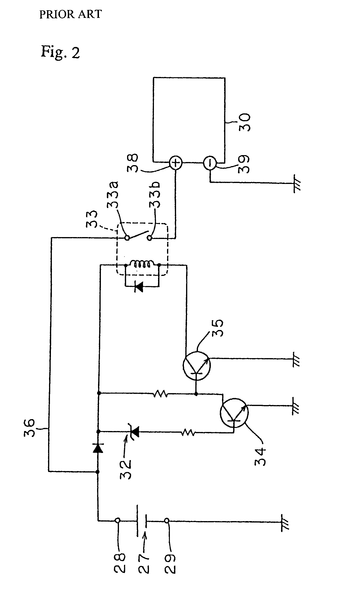
a protection circuit and power supply technology, applied in the direction of electric variable regulation, process and machine control, instruments, etc., can solve the problems of direct current power supply output b>27/b> being reduced below a predetermined normal power voltage, damage to electrical equipment, etc., to reduce manufacturing costs and simple power source protection circuits

Inactive Publication Date: 2005-12-06
ORION ELECTRIC CO LTD
View PDF8 Cites 8 Cited by
  • Summary
  • Abstract
  • Description
  • Claims
  • Application Information

AI Technical Summary

Benefits of technology

[0021]Thus, the power supply protection circuit according to the present invention can protect electrical equipments from damages due to both of an excess voltage and a reduced voltage.
[0022]In addition, transistors may be used as the above-described semiconductor-switching elements, thereby making the power source protect circuit simple and leading to reduction of manufacturing costs.

Problems solved by technology

When a voltage outputted from a direct current power source is increased for some reason or other and an excess voltage is applied to an electrical equipment, the electrical equipment operated by the direct current power supply can be damaged.
However, the protection circuit shown in FIG. 2 is unable to deal with such a case that the output of the direct current power supply 27 becomes reduced below a predetermined normal power voltage.
In general, even when a power voltage of a direct current power supply is reduced, this gives bad affects to electrical equipments.
Namely, if a power voltage is reduced, such an electrical equipment, e.g., as a TV receiving set tends to continue to operate displaying unstable video pictures, thus resulting in discomfort to viewers.

Method used


Image

  • Power supply protection circuit
  • Power supply protection circuit
  • Power supply protection circuit

Examples


Embodiment Construction

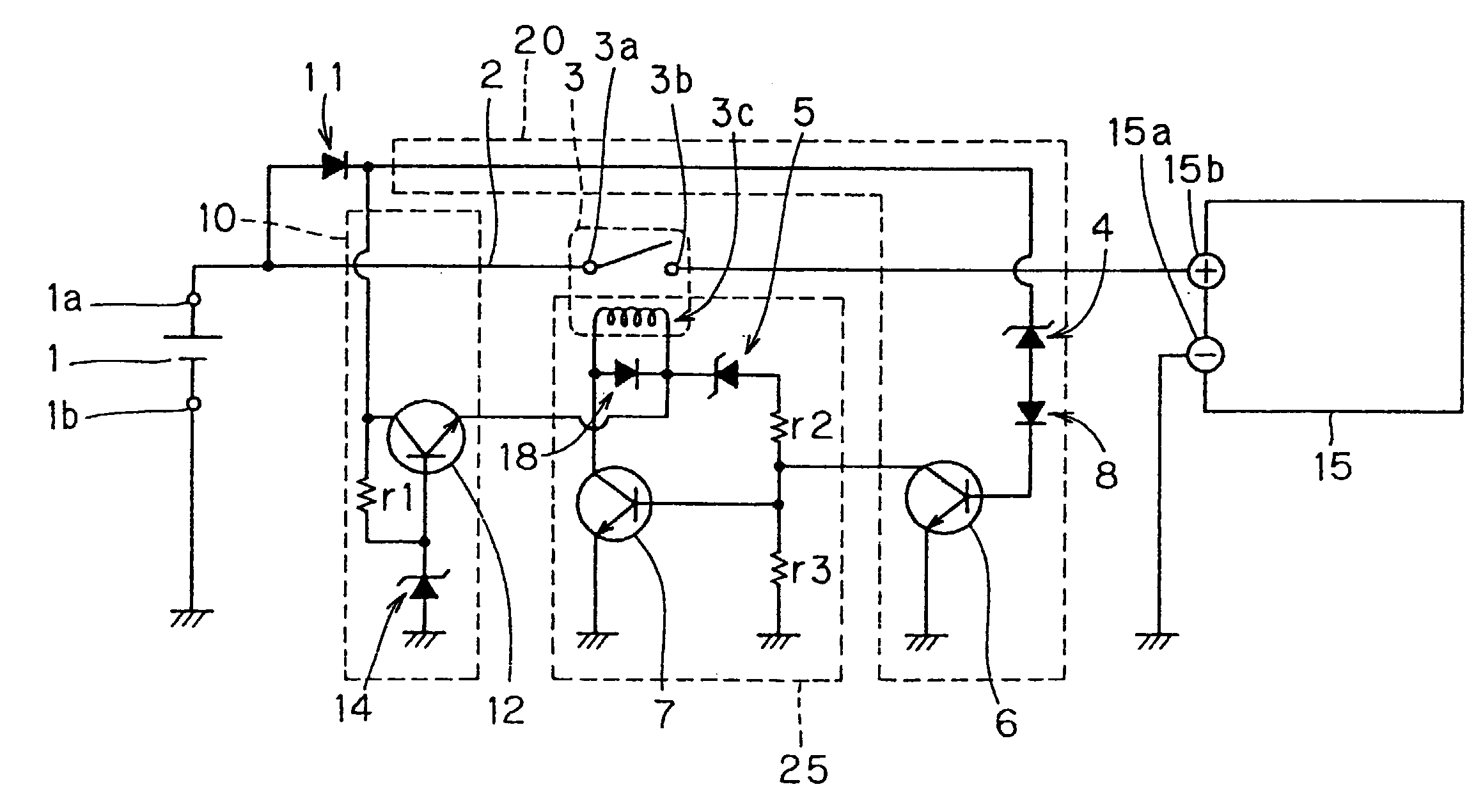
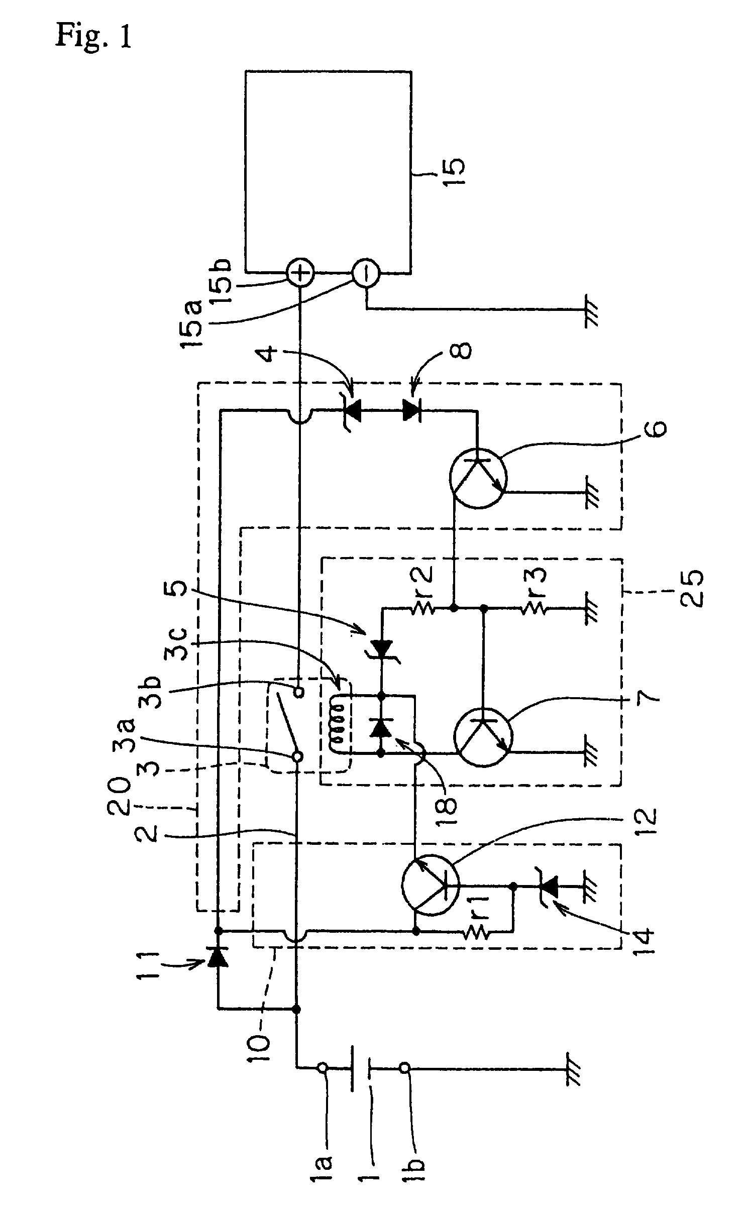
[0026]In FIG. 1, a numeral 1 depicts a direct current power supply, and a numeral 15 depicts an electrical equipment that operates with a direct current electric power supplied by the direct current power supply. The power supply protection circuit according to the present invention is disposed between the direct current power supply 1 and the electrical equipment 15.

[0027]Direct current electric power from the direct current power supply 1 is supplied via a positive terminal 1a and a negative terminal 1b. Provided the direct current power supply 1 is attached to the positive terminal 1a and the negative terminal 1b without mistaking the polarity of positive and negative of the terminals, direct current electric power is outputted so that the positive terminal 1a gets positive potential relative to the negative terminal 1b. In this case, the negative terminal 1b is grounded. The direct current power supply 1, during a normal predetermined operation, outputs a normal power voltage wi...


PUM


Abstract

A power supply protection circuit for stopping a power supply to electrical equipments in case a normal power voltage is not outputted from a direct current power supply and an excess voltage or a reduced voltage is outputted. The power supply protection circuit according to the present invention is constituted of a power source line for supplying a direct current power, via relay contacts of a relay, to an electrical equipment, a first circuit for detecting an excess voltage and a reduced voltage, a second circuit, and a relay operation circuit.

Description

BACKGROUND OF THE INVENTION[0001]The present invention relates to an operation of an electrical equipment by a direct current power supply and more particularly, to a power supply protection circuit to stop supplying a power to an electrical equipment in case a normal power voltage is not outputted from a direct current power supply.PRIOR ART[0002]When a voltage outputted from a direct current power source is increased for some reason or other and an excess voltage is applied to an electrical equipment, the electrical equipment operated by the direct current power supply can be damaged. Accordingly, to protect an electrical equipment from such an excess voltage, in prior arts, a power supply protection circuit is provided in an input path from a direct current power supply to an electrical equipment.[0003]FIG. 2 is a circuit diagram showing one example of a conventional power supply protection circuit. In FIG. 2, a numeral 27 depicts a direct current power supply. A direct current e...

Claims


Application Information

Patent Timeline
Patent Type & Authority Patents(United States)
IPC IPC(8): G05F1/10H02H11/00H02H3/20
CPCH02H3/207H02H3/202
Inventor TSUKASAKI, NORIKAZUKUMANO, MITSUO
Owner ORION ELECTRIC CO LTD
Why Eureka
Try Eureka