
Track jump apparatus capable of varying moving pulse and braking pulse

a track jumping and control method technology, applied in the direction of digital signal error detection/correction, instruments, recording signal processing, etc., can solve the problems of insufficient distance of track jumping of the objective lens, inability to stabilize the track jumping operation, and excessive distance of the objective lens

Inactive Publication Date: 2005-12-06
SONY CORP
View PDF12 Cites 1 Cited by
  • Summary
  • Abstract
  • Description
  • Claims
  • Application Information

AI Technical Summary

Benefits of technology

[0008]It is an object of the present invention to provide a disk drive apparatus and a track jumping control method by which a track jumping operation of an objective lens is stabilized.
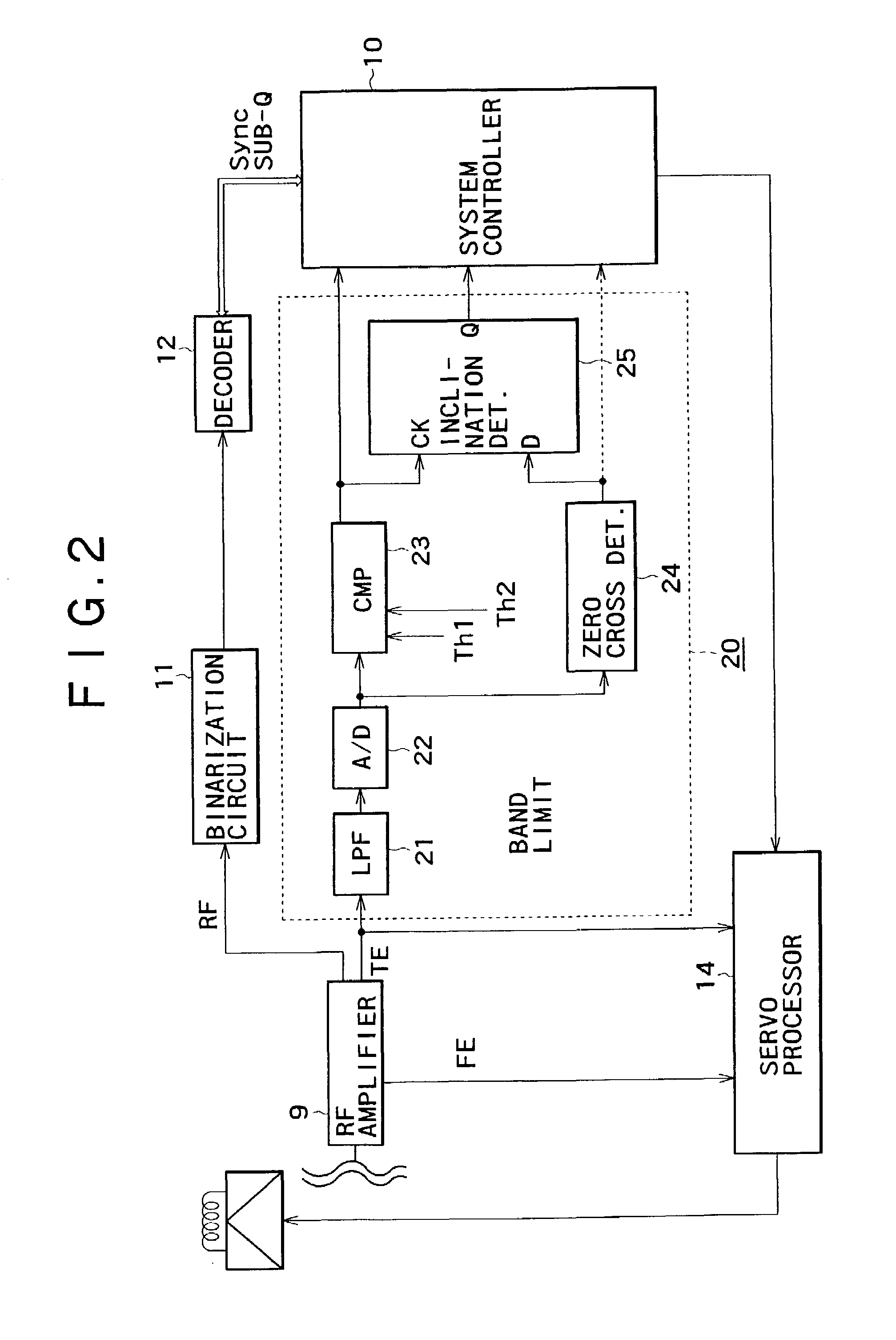
[0023]Consequently, such a situation that the object lens moves excessively upon track jumping when the moving direction of the object lens which moves by a tracking operation and the track jumping direction coincide with each other and such another situation that the object lens moves insufficiently upon track jumping when the moving direction of the object lens and the track jumping direction are opposite to each other can be eliminated. As a result, a stabilized track jumping operation can be achieved.

Problems solved by technology

However, usually in a disk drive apparatus, it is considered that the objective lens seldom starts its track jumping operation from its stationary state because, since periodical displacement of tracks is caused by some eccentricity of a disk, the objective lens is normally moved so that it may follow up a track through a tracking servo operation by control based on a tracking error signal and also external vibrations may possibly have an influence on the objective lens.
If, while the objective lens is moving through a tracking servo operation against eccentricity or disturbance in this manner, the moving direction of the objective lens and the direction of track jumping become the same direction, then the distance of the track jumping of the objective lens may become excessive.
On the other hand, if the two directions become opposite to each other, then the distance of the track jumping of the objective lens may become insufficient.
Thus, the conventional disk drive apparatus is disadvantageous in that the track jumping operation is not stabilized.

Method used


Image

  • Track jump apparatus capable of varying moving pulse and braking pulse
  • Track jump apparatus capable of varying moving pulse and braking pulse
  • Track jump apparatus capable of varying moving pulse and braking pulse

Examples


Embodiment Construction

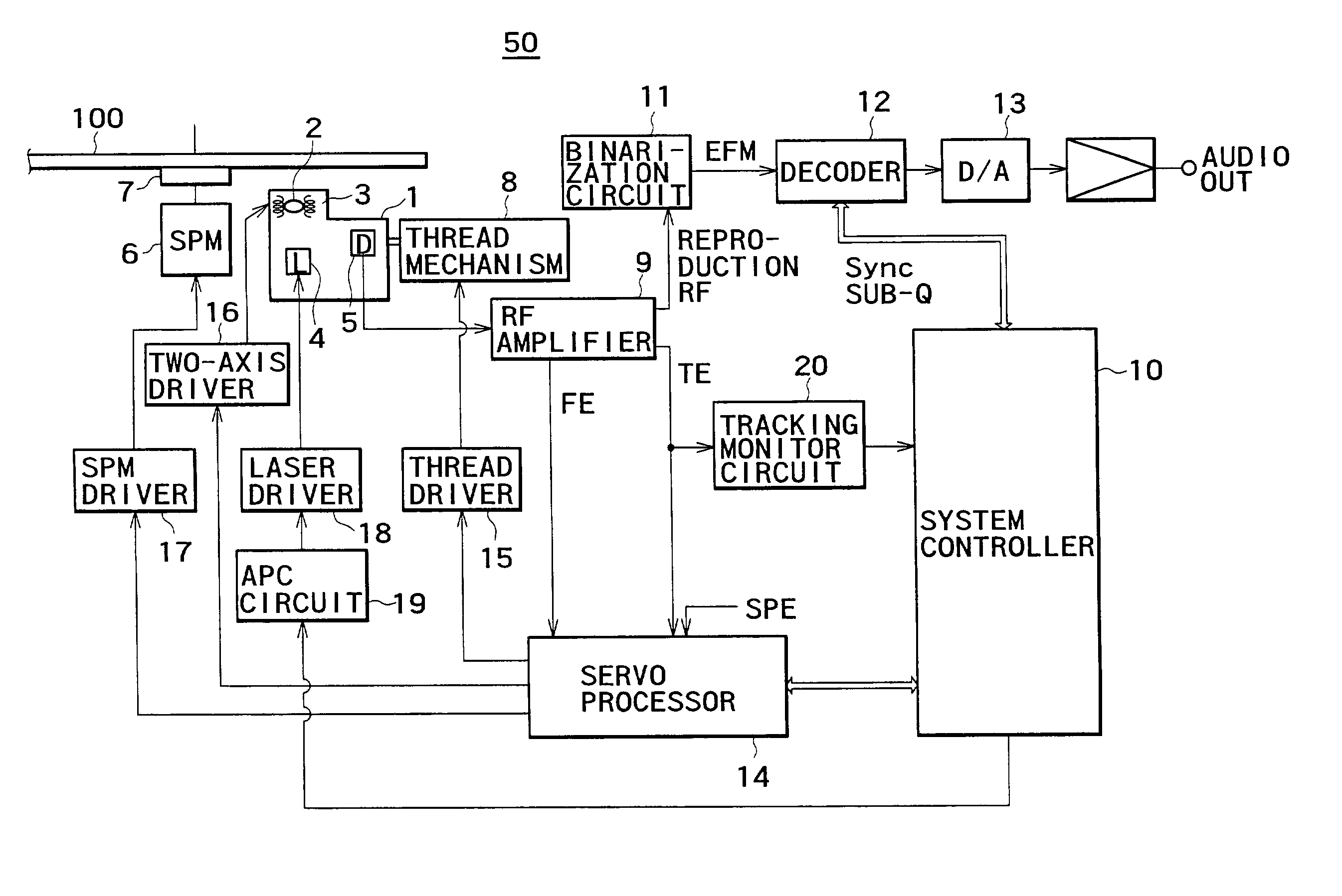
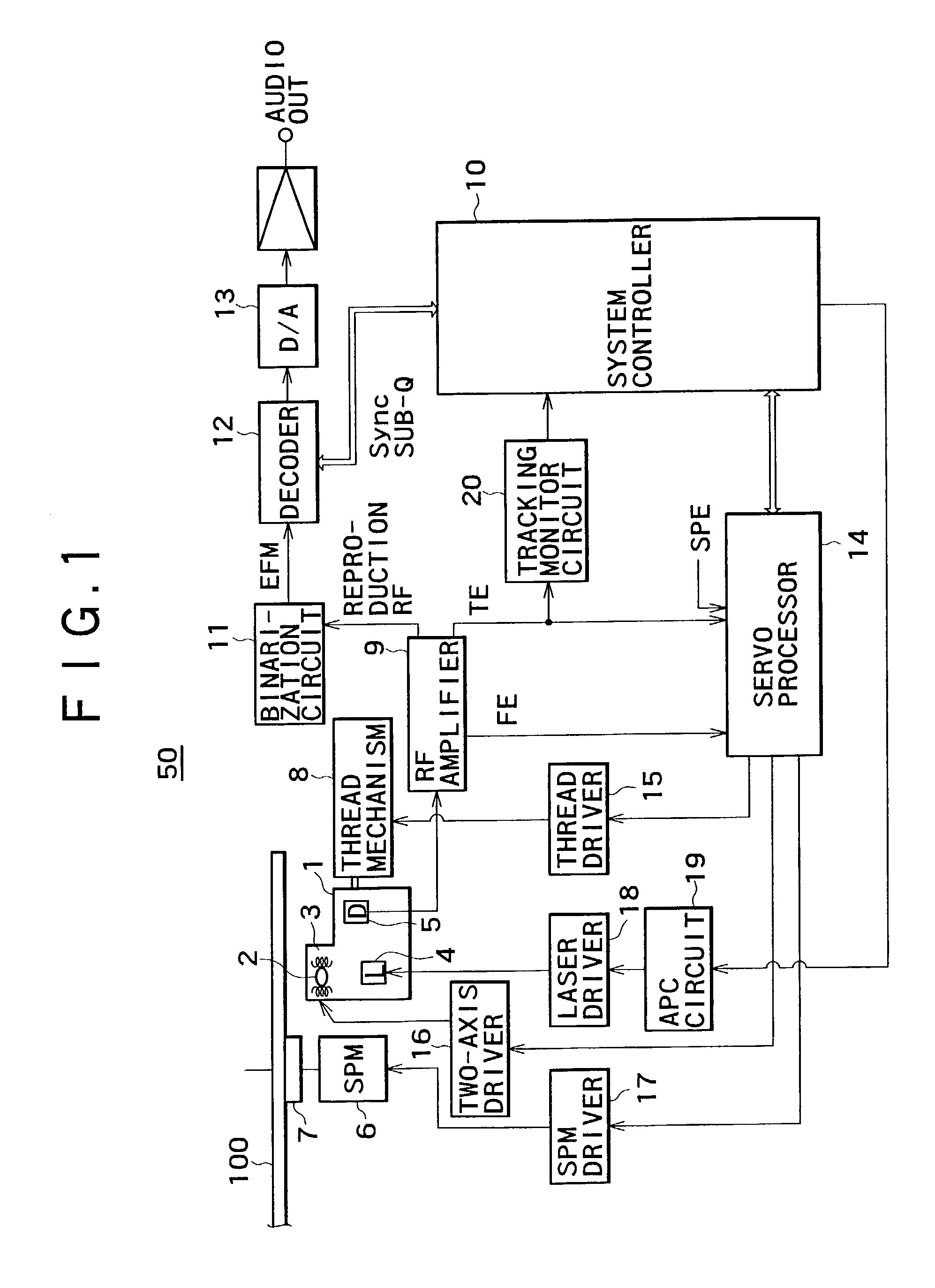
[0031]Referring first to FIG. 1, there is shown an internal configuration of a disk reproduction apparatus 50 to which the present invention is applied. A disk 100 is placed on a turntable 7 and is driven to rotate at a constant linear velocity (CLV) or a constant angular velocity (CAV) by a spindle motor 6 upon reproduction operation. During rotation of the disk 100, a pickup 1 reads out data recorded in the form of embossed pits, coloring matter pits, phase change pits or the like on the disk 100. It is to be noted that, in the following description of the present embodiment, it is assumed that the disk reproduction apparatus 50 is a CD (Compact Disk) player of the CLV type.

[0032]A laser diode 4 serving as a laser light source, a photo-detector 5 for detecting reflection light, an objective lens 2 which is an output end of the laser light, and an optical system for irradiating a laser beam from the laser diode 4 on a recording face of the disk 100 through the objective lens 2 and ...


PUM

PropertyMeasurementUnit
forceaaaaaaaaaa
widthaaaaaaaaaa
distanceaaaaaaaaaa

Abstract

A disk drive apparatus is disclosed for stabilizing a track jumping operation of an objective lens. The disk drive apparatus includes a detection section for detecting the direction that object lens is being moved by a tracking operation, and a discrimination section for discriminating the direction of the track jumping operation. A track jump movement then performed based on the detection of movement and discrimination of the track jump operation. Therefore, the track jump is stabilized without being influenced by the movement of the objective lens by the tracking operation.

Description

BACKGROUND OF THE INVENTION[0001]The present invention relates to a disk drive apparatus and a track jumping control method for a disk drive apparatus.[0002]In a conventional disk drive apparatus, in order to cause an objective lens to perform a track jumping operation, a track jump signal composed of a moving pulse signal and a braking pulse signal is produced and used for the track jumping operation.[0003]The moving pulse signal acts to apply force upon the objective lens to move it in a track jumping direction. On the other hand, the braking pulse signal acts to apply force upon the objective lens to move it in the direction opposite to the track jumping direction, that is, to brake the objective lens. In other words, the moving pulse signal accelerates the objective lens in the track jumping direction whereas the braking pulse signal decelerates the objective lens.[0004]In conventional disk drive apparatus, usually the moving pulse signal and the braking pulse signal have an equ...

Claims


Application Information

Patent Timeline
Patent Type & Authority Patents(United States)
IPC IPC(8): G11B7/085G11B21/08G11B7/09
CPCG11B7/08505G11B7/08529G11B7/09
Inventor SEKINE, KAZUHIROYUNOKI, HIROTOMO
Owner SONY CORP
Learn More