Digital broadcasting apparatus

a digital broadcasting and apparatus technology, applied in the field of digital broadcasting apparatus, can solve the problems of high possibility of transmission signal peaks and difficult to secure the dynamic range of the front-end amplifier in the receiver, and achieve the effect of small dynamic range of the generated broadcasting signal and easy securement of the dynamic range of the front-end amplifier circui

Inactive Publication Date: 2005-12-06
SONY CORP +1
View PDF7 Cites 62 Cited by
  • Summary
  • Abstract
  • Description
  • Claims
  • Application Information

AI Technical Summary

Benefits of technology

[0017]In the present invention, either the parameter of the frequency interleaving of the main signal or the initial value of the random number code for generating a pseudo-random sequence for sub-signal modulation is controlled according to the broadcasting frequency. As a result, it is possible to keep the dynamic range of the generated broadcasting signal as small as possible. Therefore, it is possible to easily secure a dynamic range of a front-end amplification circuit in a receiver.

Problems solved by technology

From this, when viewing the entire signals in a channel, because there are many groups of carriers having the same phases, there arises a disadvantage that the possibility of occurrence of peaks in a transmission signal is high, and it is difficult to secure the dynamic range of the front-end amplifier in a receiver.

Method used


Image

  • Digital broadcasting apparatus
  • Digital broadcasting apparatus
  • Digital broadcasting apparatus

Examples


first embodiment

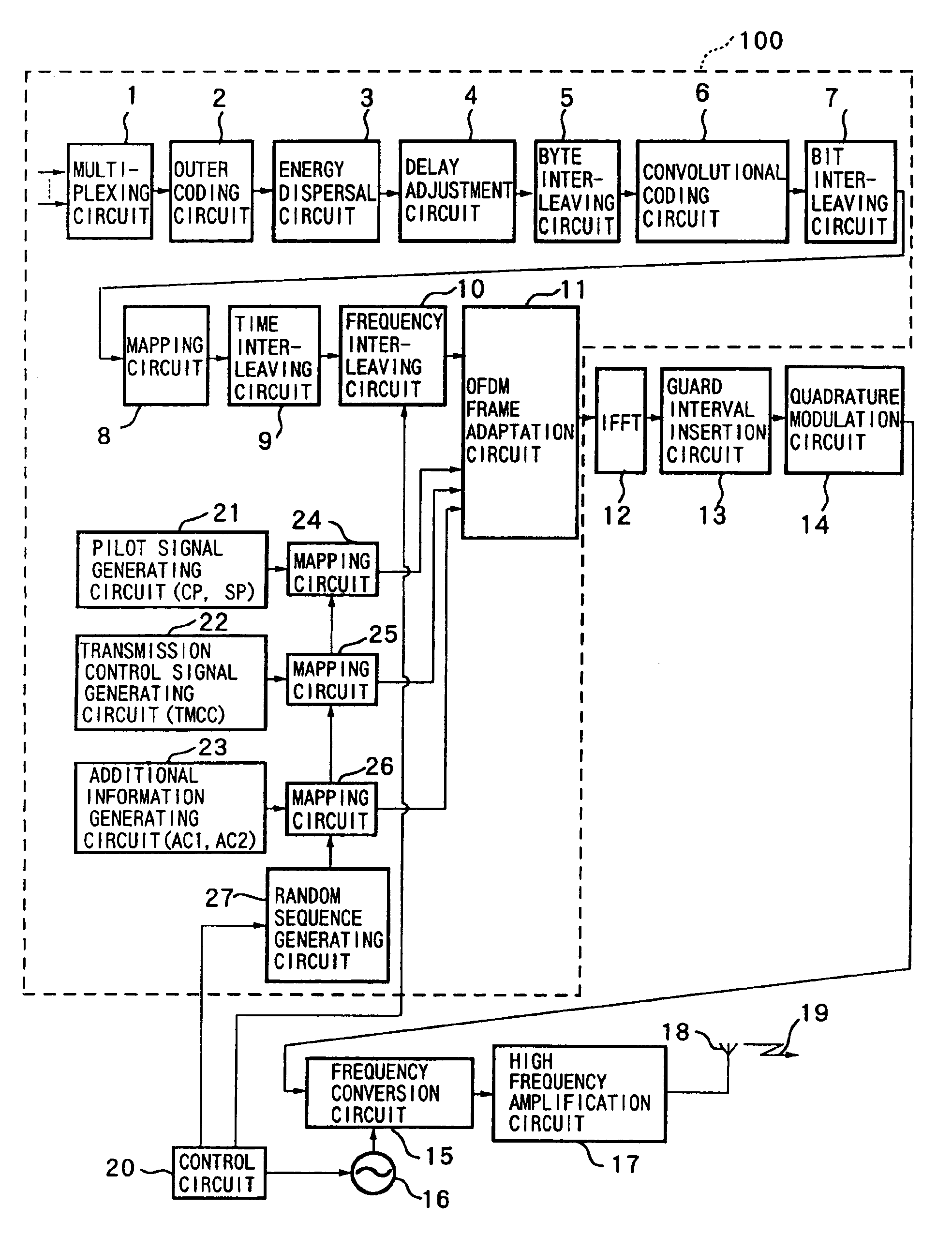
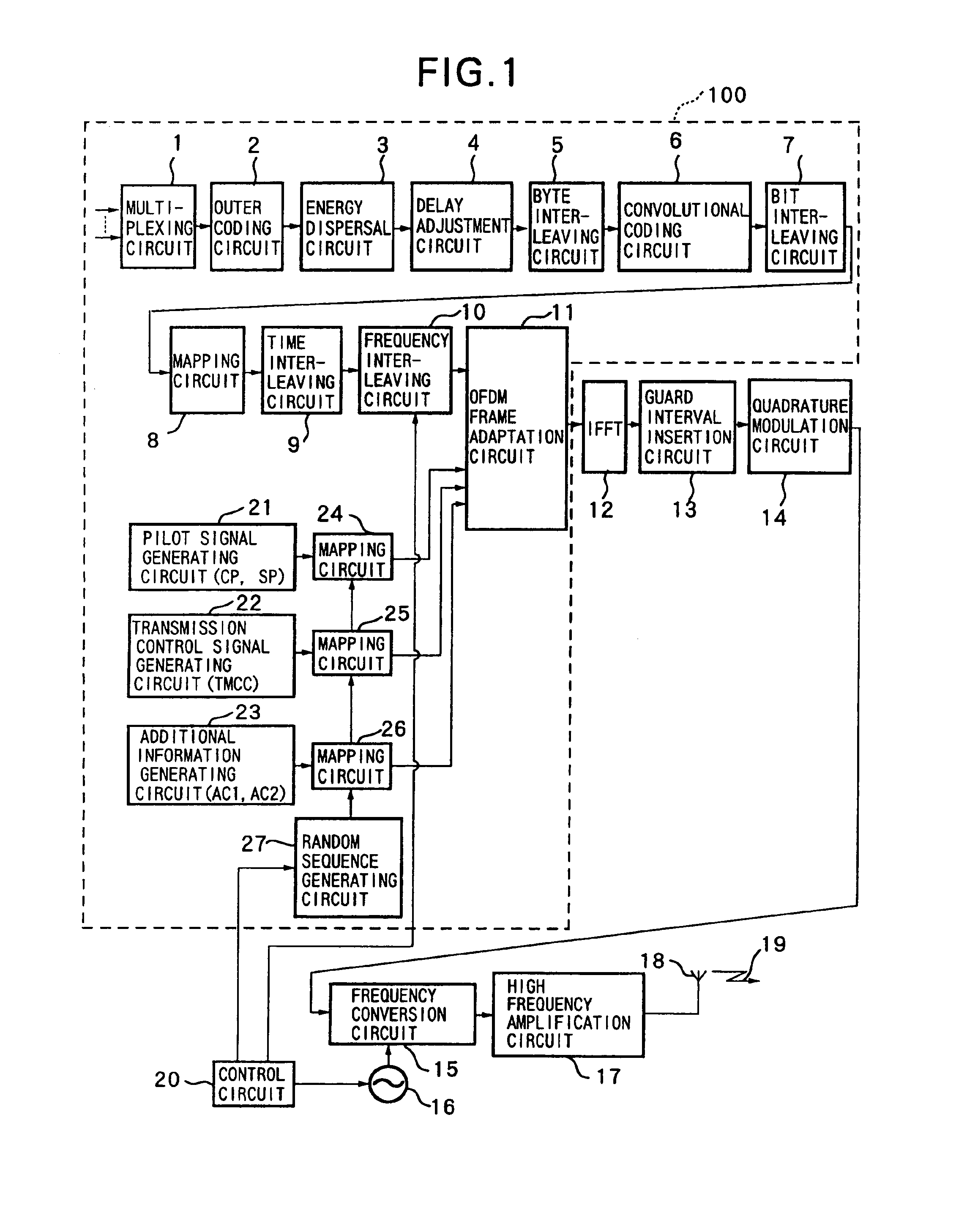
[0024]FIG. 1 is a circuit diagram of a first embodiment of a digital broadcasting apparatus according to the present invention.

[0025]As shown in this figure, the digital broadcasting apparatus of the present embodiment is comprised of a broadcasting signal processing circuit 100 for processing one segment of a broadcasting signal, an inverse Fourier transform circuit 12 (IFFT), a guard interval insertion circuit 13, a quadrature modulation circuit 14, a frequency conversion circuit 15, a RF (radio frequency) signal oscillating circuit 16, a high frequency amplification circuit 17, a transmission antenna 18, and a control circuit 20.

[0026]Next, the circuits making up the digital broadcasting apparatus of the present embodiment will be explained.

[0027]The broadcasting signal processing circuit 100, as shown in this figure, is comprised of a multiplexing circuit 1, an outer coding circuit 2, an energy dispersal circuit 3, a delay adjustment circuit 4, a byte interleaving circuit 5, a c...

second embodiment

[0063]FIG. 4 is a circuit diagram of a second embodiment of a digital broadcasting apparatus according to the present invention.

[0064]In the first embodiment of the present invention described above, the broadcasting signal processing circuit 100 basically processes 1-segment broadcasting signals. In the digital broadcasting apparatus of the present invention, however, it is possible to modulate not only single segment but also a plurality of narrow-band ISDB-T signals together. In this case, the circuits after the inverse Fourier transform circuit 12 can be shared by the plurality of narrow-band ISDB-T signals. The present embodiment is configured based on this.

[0065]As shown in FIG. 4, the digital broadcasting apparatus of the present embodiment is comprised of broadcasting signal processing circuits 100, 101, and 102, a multiplexing circuit (MUX) 110, an inverse Fourier transform circuit (IFFT) 12, a guard interval insertion circuit 13, a quadrature modulation circuit 14, a frequ...


PUM


Abstract

A frequency interleaving circuit frequency-interleaves main signals generated according to sound data by parameters set according to frequencies of transmission channels. A sub-signal generating circuit generates sub-signals for transmission control including pilot signals. Mapping circuits modulate the sub-signals by using pseudo-random sequences generated based on initial values of random codes set according to frequencies of transmission channels. The frequency-interleaved main signals and the sub-signals modulated by the mapping circuits are OFDM-modulated. Then, they are converted to the frequencies of the transmission channels. An increase of a dynamic range of transmission signals can be suppressed by controlling the initial values of random codes set.

Description

[0001]This Application is a 371 of PCT / JP00 / 01091 Feb. 25, 2000.TECHNICAL FIELD[0002]The present invention relates to a digital broadcasting apparatus, in particular to a digital broadcasting apparatus for digital terrestrial sound broadcasting.BACKGROUND ART[0003]As provisional systems of digital terrestrial television broadcasting and digital terrestrial sound broadcasting, broadcasting systems called the broadband ISDB-T system and narrow-band ISDB-T system have been proposed. These broadcasting systems are compatible with each other. At a bandwidth of about 429 kHz, which is obtained by dividing into 14 the 6 MHZ frequency band assigned to Japanese domestic television channels, an OFDM-(orthogonal frequency division multiplexing) modulated basic transmission unit called segment is formed. This segment is used for digital terrestrial television broadcasting or digital terrestrial sound broadcasting.[0004]Signals of segment are OFDM-modulated. As the number of OFDM carriers of the...

Claims


Application Information

Patent Timeline
Patent Type & Authority Patents(United States)
IPC IPC(8): H04H20/72H04L27/26
CPCH04H20/72H04L27/2618H04B2201/70706
Inventor IKEDA, YASUNARIHYAKUDAI, TOSHIHISAOKADA, TAKAHIROIKEDA, TAMOTSUKURODA, TORUIAI, NAOHIKOTSUCHIDA, KENICHISASAKI, MAKOTO
Owner SONY CORP
Why Eureka
Try Eureka