Steerable cardiac pacing and sensing catheter and guidewire for implanting leads

a catheter and cardiac pacing technology, applied in the field of implantable leads, can solve the problems of inability to meet the capture threshold or presence of diaphragmatic stimulation

Inactive Publication Date: 2005-12-06
PACESETTER INC
View PDF11 Cites 80 Cited by
  • Summary
  • Abstract
  • Description
  • Claims
  • Application Information

AI Technical Summary

Benefits of technology

[0008]An assist device for an implantable cardiac stimulation lead system includes a handle for a steerable guidewire system. An inner conductive guidewire with a distal tip electrode is pre-shaped into a free state curved configuration. An outer sheath is coaxial with the guidewire and relatively slidable between a first position restraining the guidewire to a straight condition and a second position withdrawn from a freed length of the guidewire allowing it to assume i

Problems solved by technology

Many times, a physician would spend a significant amount of time to place the lead only to f

Method used


Image

  • Steerable cardiac pacing and sensing catheter and guidewire for implanting leads
  • Steerable cardiac pacing and sensing catheter and guidewire for implanting leads
  • Steerable cardiac pacing and sensing catheter and guidewire for implanting leads

Examples


Embodiment Construction

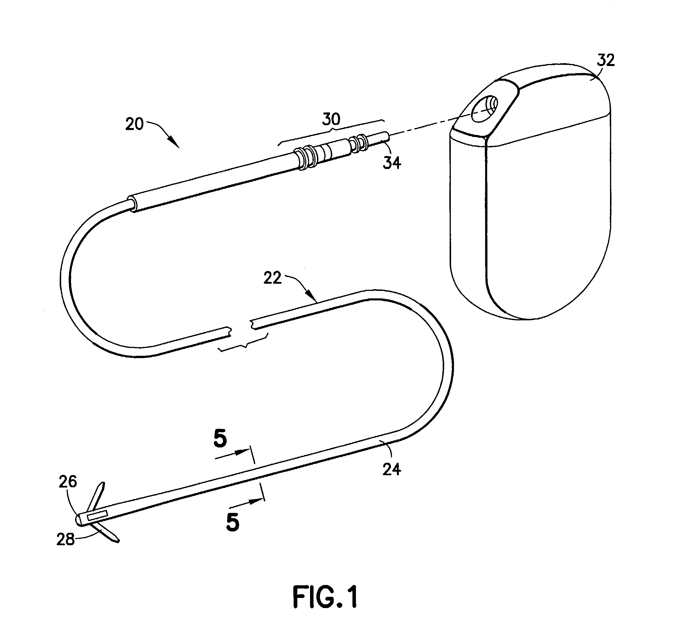
[0026]Turn now to the drawings and, initially to FIG. 1 which generally illustrates a body implantable lead system 20 of the endocardial type incorporating features of the present invention. Although the present invention will be described with reference to the embodiments shown in the drawings, it should be understood that the present invention can be embodied in many alternate forms or embodiments. In addition, any suitable size, shape or type of elements or materials consistent with the invention could be used.

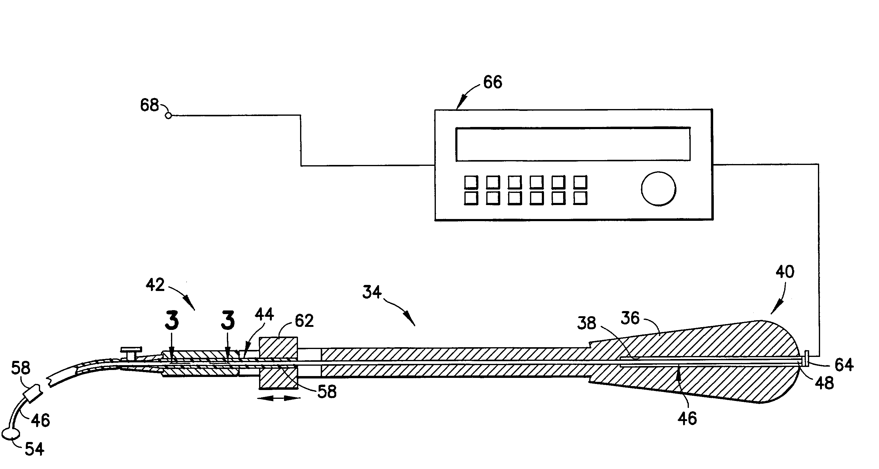
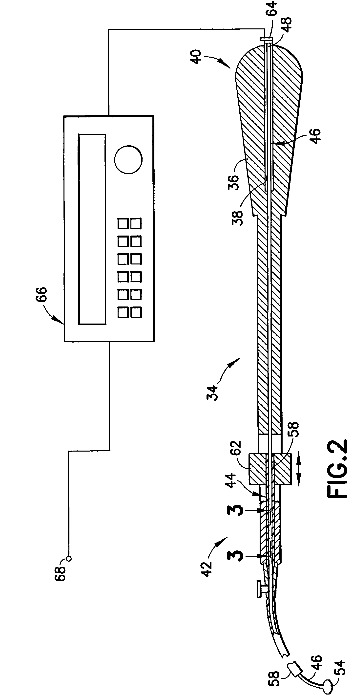
[0027]The lead system 20, illustrated to be of a unipolar design, but not intended to be limiting of the invention, includes a lead body 22 with an insulating sheath 24 interconnecting a distal electrode 26 secured adjacent an interior wall of an organ such as the heart by means, for example, of fixing tines 28 which engage the tissue or trabeculae of the heart. The lead system 20 also includes an electrical connector 30 at a proximal end to which can be attached a source o...


PUM

PropertyMeasurementUnit
Lengthaaaaaaaaaa
Diameteraaaaaaaaaa
Flexibilityaaaaaaaaaa

Abstract

An assist device for an implantable cardiac stimulation lead system includes a handle for a steerable guidewire system. An inner conductive guidewire with a distal tip electrode is pre-shaped into a free state curved configuration. An outer sheath is coaxial with the guidewire and relatively slidable between a first position restraining the guidewire to a straight condition and a second position withdrawn from a freed length of the guidewire allowing it to assume its free state curved condition. A collar on the outer sheath is movable along the handle for moving the sheath between the first and second positions. An electrical terminal is in electrical continuity with the tip electrode such that a pacing system analyzer connected between the electrical terminal and a reference electrode in the body is operable for seeking a location at which optimal pacing parameters can be determined prior to final implantation of the lead system.

Description

FIELD OF THE INVENTION[0001]The present invention relates generally to an implantable lead for use with an implantable medical device and, more particularly, to a technique for seeking a location at which optimal pacing parameters can be determined prior to final implantation of the lead.BACKGROUND OF THE INVENTION[0002]Permanently implantable electrical lead systems are used in conjunction with implantable medical devices, such as pacemakers and defibrillators. In these applications the lead is used to transmit electrical signals to and / or from the medical device. Leads of this type may be chronically implanted and are expected to exhibit a long service life in a hostile environment of the human body. Cardiac stimulation leads are usually implanted via the cardiovascular venous system such that the distal end of the lead is positioned at an appropriate site within a heart chamber or within cardiac coronary vasculature which overlie the epicardial surface of the heart.[0003]Cardiac ...

Claims


Application Information

Patent Timeline
IPC IPC(8): A61B5/042A61M25/00A61M25/01A61N1/00A61N1/05
CPCA61M25/0045A61M25/0136A61M25/0152A61N1/056A61B5/042A61M25/005A61M2025/0039A61M2025/004A61N2001/0578A61B5/283
Inventor TSUTSUI, DUANECHITRE, YOUGANDH
Owner PACESETTER INC
Why Eureka
Try Eureka