
Device for remote power feeding a terminal in a telecommunication network, and a concentrator and a repreater including the device

a technology of remote power and terminal, which is applied in the field of telecommunication network, can solve the problems of sending and receiving circuits, risk of damage to the electrical circuit of the terminal, and current flowing in the resistor can destroy the circuit, so as to achieve the effect of easy comparison of current and accuracy

Inactive Publication Date: 2005-12-06
WI LAN INC
View PDF12 Cites 83 Cited by
  • Summary
  • Abstract
  • Description
  • Claims
  • Application Information

AI Technical Summary

Benefits of technology

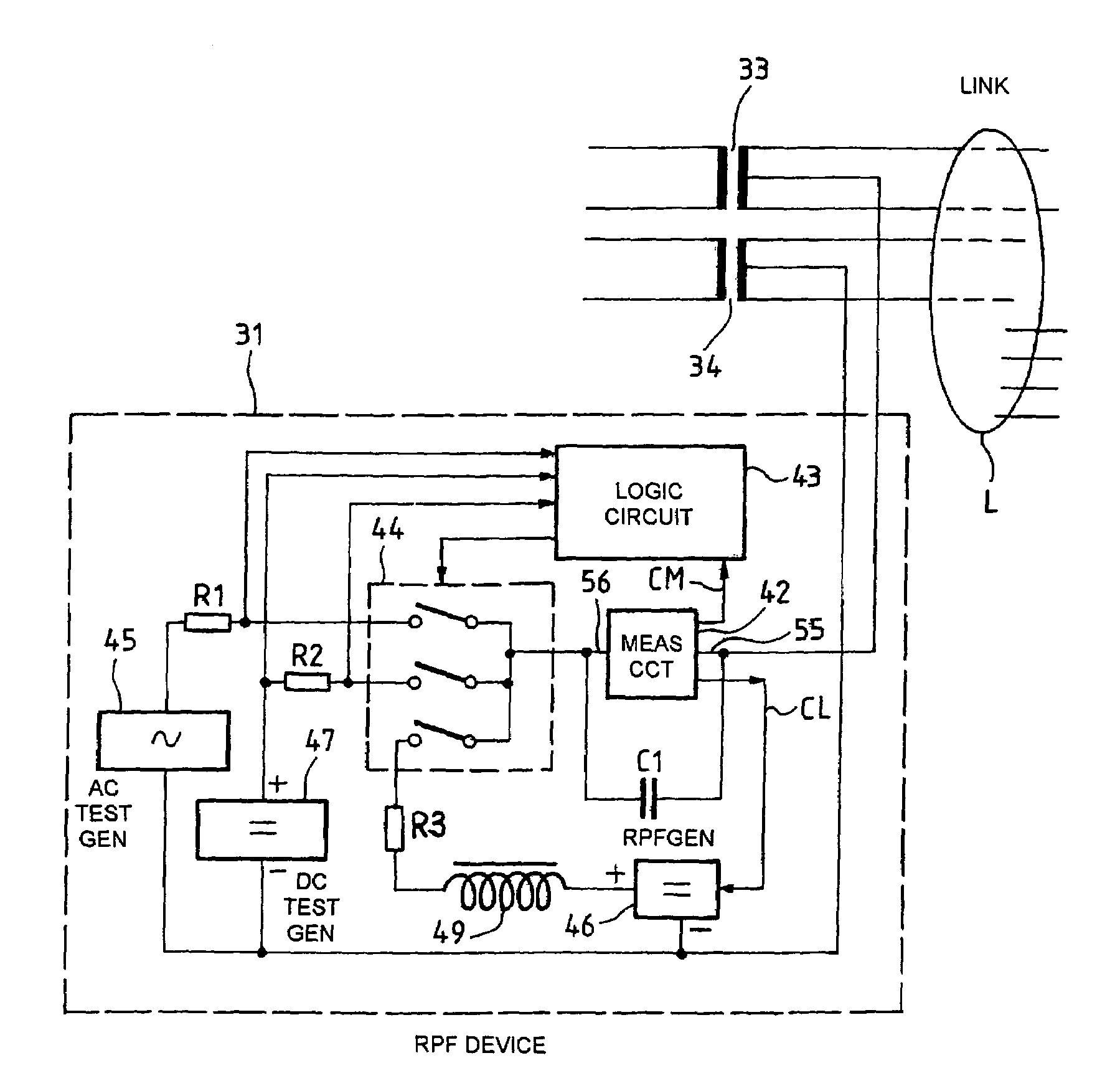
"The invention is a device that supplies power to a device in a telecommunications network. The device has a measuring device that checks if the power feed current is greater than a certain threshold. This device has a resistive circuit that has a lower resistance when the current is very high, which compensates for the increased voltage drop caused by the high current. The device can also switch between two resistive circuits to compare the current with two different thresholds. The invention also includes a repeater and a concentrator that use this remote power feed device. The technical effect of this invention is to provide a reliable and accurate power feed to a terminal in a telecommunications network."

Problems solved by technology

In both cases, providing a remote power feed to the terminal via the computer local area network has the disadvantage that the remote power feed device powers a terminal “blind”.
There is a risk of damaging the electrical circuits of that terminal.
If a relatively high supply voltage, for example 48 volts, is applied to that combination of resistors and capacitors, or to the resistors connected to the center taps of the transformers, the current flowing in the resistors can destroy them, and the send and receive circuits.
A similar problem arises in producing a subscriber line interface card for a telephone exchange.

Method used


Image

  • Device for remote power feeding a terminal in a telecommunication network, and a concentrator and a repreater including the device
  • Device for remote power feeding a terminal in a telecommunication network, and a concentrator and a repreater including the device
  • Device for remote power feeding a terminal in a telecommunication network, and a concentrator and a repreater including the device

Examples


Embodiment Construction

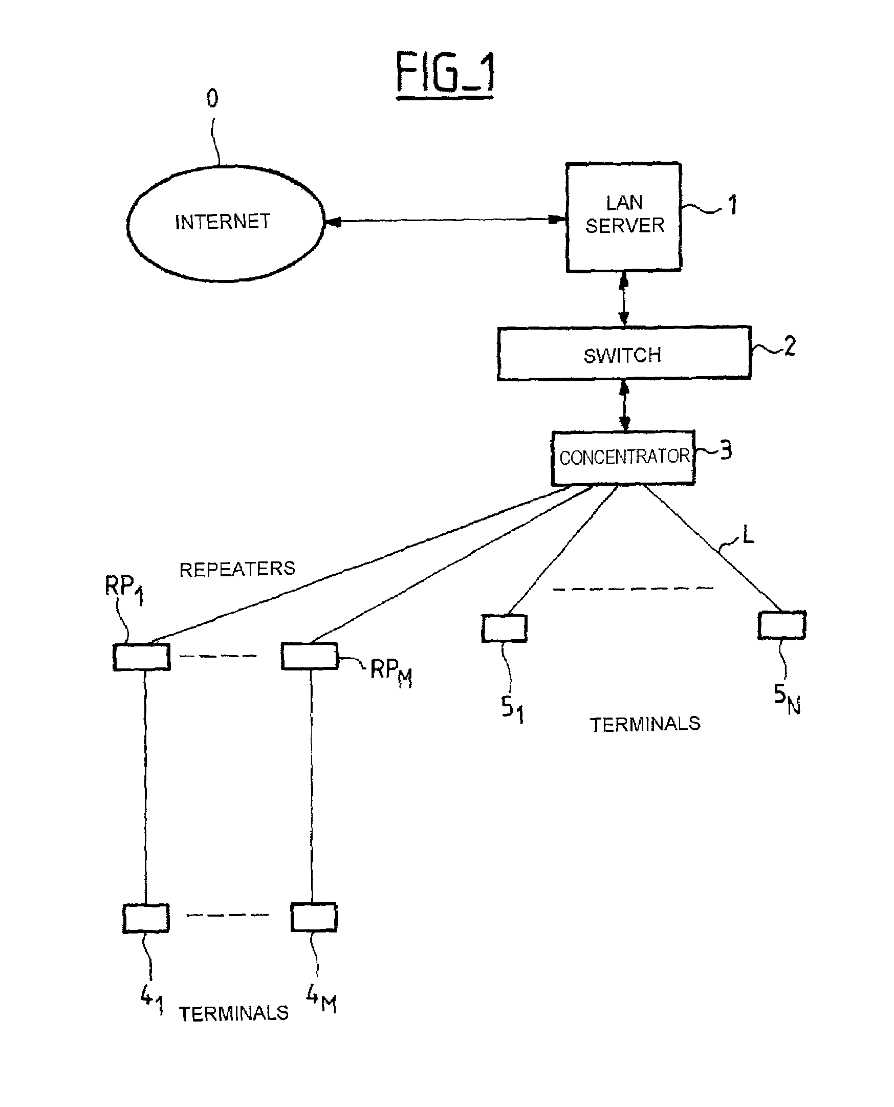
[0033]FIG. 1 is a block diagram of part of one embodiment of an Ethernet computer local area network including a concentrator 3 and repeaters RP1, . . . , RPM each incorporating one embodiment of a remote power feed device according to the invention. The local area network further includes a local area network server 1, a switch 2, M terminals 41 to 4M connected to the concentrator 3 via the respective repeaters RP1, . . . , RPM, because of the distance, and N terminals 51 to 5N connected directly to the concentrator 3. The terminals are telephones operating in voice over IP (VoIP) mode, for example.

[0034]The server 1 is connected to the Internet 0. It sends and receives TCP / IP packets. The packets of a given call are routed via the switch 2 and the concentrator 3 to a terminal such as the terminal 41, which is connected to the concentrator 3 via an 8-wire link L with RJ45 connectors.

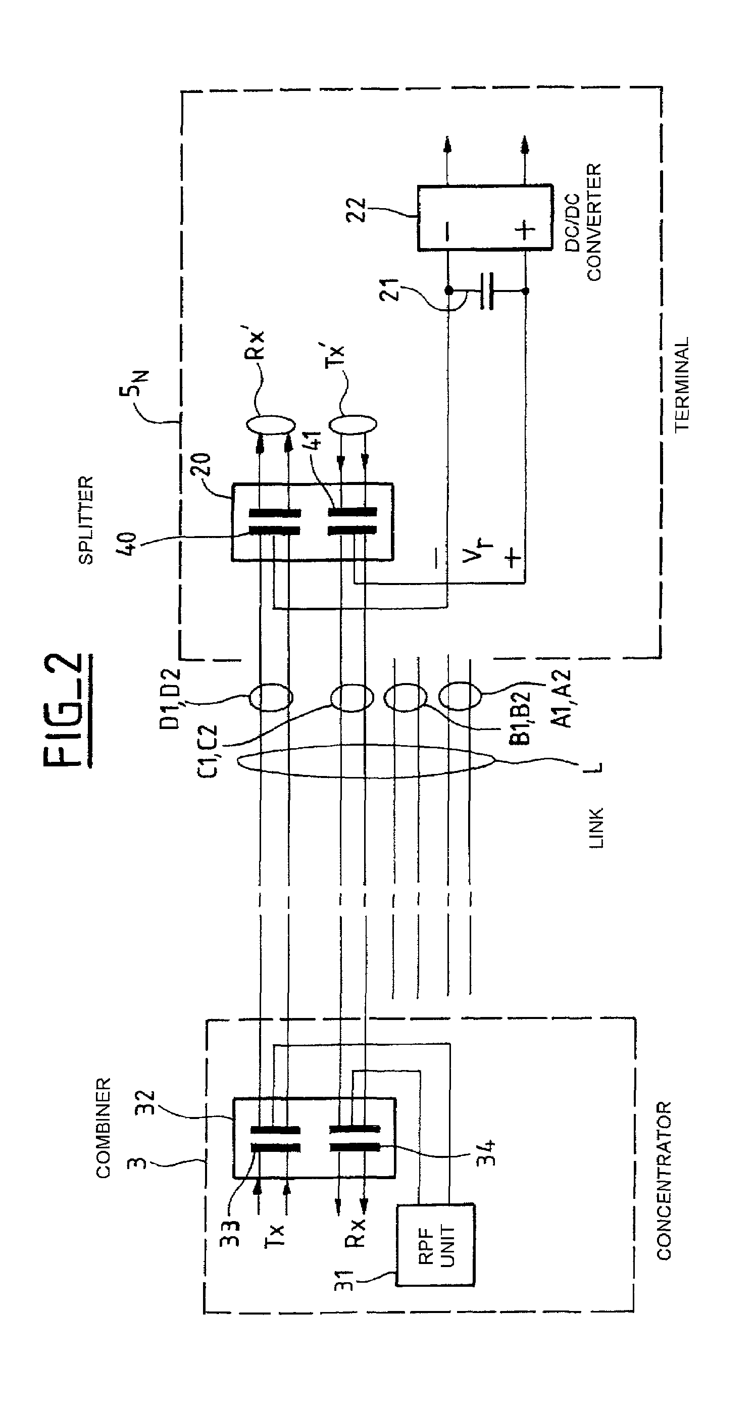
[0035]FIG. 2 shows a block diagram of one embodiment of a remote power feed device in the concentrat...


PUM


Abstract

A first resistor is connected in parallel with a second resistor having a lower resistance than the first resistor. The voltage at the terminal of the first resistor is compared with a first threshold voltage, and the voltage at the terminals of the second resistor is compared with a second threshold voltage. A switching device either connects the first resistor in series in a remote power feed circuit, if the switching device detects that the remote power feed current is less than a third threshold current that is between the first and second threshold currents, or connects the second resistor and the first resistor, connected in parallel, in series in the remote power feed circuit if the switching device detects that the remote power feed current is greater than the third threshold current.

Description

CROSS-REFERENCE TO RELATED APPLICATIONS[0001]This application is based on French Patent Application No. 01 00 168 filed Jan. 8, 2001, the disclosure of which is hereby incorporated by reference thereto in its entirety, and the priority of which is hereby claimed under 35 U.S.C. §119.BACKGROUND OF THE INVENTION[0002]1. Field of the Invention[0003]The present invention relates generally to a telecommunication network, in particular a computer local area network, for example an Ethernet network, or a telephone network. To be more precise, the invention relates to a device for providing a remote power feed to a terminal in this kind of network.[0004]2. Description of the Prior Art[0005]Terminals connected to a computer local area network (for example: personal computers, printers, etc) are conventionally powered locally from the mains electrical power supply. It is desirable for some terminals to receive a remote power feed via the link used to send and receive data. To facilitate addit...

Claims


Application Information

Patent Timeline
Patent Type & Authority Patents(United States)
IPC IPC(8): H04L12/10H04M19/08H04Q3/42
CPCH04L12/10H04M19/08
Inventor JAEGER, REMYMEDLICOTT, MARKVERGNAUD, GERARDGUNTZ, VINCENT
Owner WI LAN INC
Learn More