
Mammographic paddle

a compression device and breast technology, applied in mammography, medical science, diagnostics, etc., can solve the problems of affecting the quality of images taken with longer exposure times, affecting the quality of images, and reducing the quality of images taken. , to achieve the effect of compressing the mid breast and preventing the slippage of breast tissu

Inactive Publication Date: 2005-12-13
AMERICAN MAMMOGRAPHICS
View PDF10 Cites 26 Cited by
  • Summary
  • Abstract
  • Description
  • Claims
  • Application Information

AI Technical Summary

Benefits of technology

[0017]Consequently, it is a primary object of the present invention to provide a mammographic paddle which may more effectively compress the mid breast and breast tissue toward the nipple end, while preventing slippage of breast tissue from the field of view of the detector towards the chest wall end.
[0018]It is another object of the invention to provide a device which provides more uniform compression for the entire breast.

Problems solved by technology

These prior art compression devices used with conventional mammography systems produce non-uniform breast compression with the greatest compression closest to the chest wall and the least compression towards the nipple where the breast is not as thick.
These compression paddles also unfortunately permit movement of the breast tissue in the mid breast and in the nipple end of the breast during imaging which causes blurring of the image, because of insufficient compression.
Those images taken with longer exposure times, such as about two or more seconds, are particularly often adversely affected.
Additionally, these prior art compression paddles can cause patient discomfort near the chest wall where the compression surface applies the greatest compression.
These curves are not believed to optimally compress the breast as the nipple end of the breast is undercompressed due to the concave portion located above the nipple end.
An additional drawback would be the breast tissue at chest wall end would tend to be pushed back out of the field of view of the imager.
Since the paddle is level at the end of the process, it is not believed to be optimally oriented to compress the breast.
Furthermore, due to the conical shape of the breast, during final compression the paddle will end up angled downwardly from the chest wall to the nipple thereby pushing the breast toward the chest wall, possibly pushing some of the breast out of an image.
While the Bennett paddle achieves improved compression of the breast without significantly displacing any breast tissue backward out of the field of view at the chest wall end, this device still has a number of disadvantages.
The breast is very thick in this area which in itself often makes good imaging difficult.
If there is suboptimal compression here, small cancers might not be detected.

Method used


Image

  • Mammographic paddle
  • Mammographic paddle
  • Mammographic paddle

Examples


Embodiment Construction

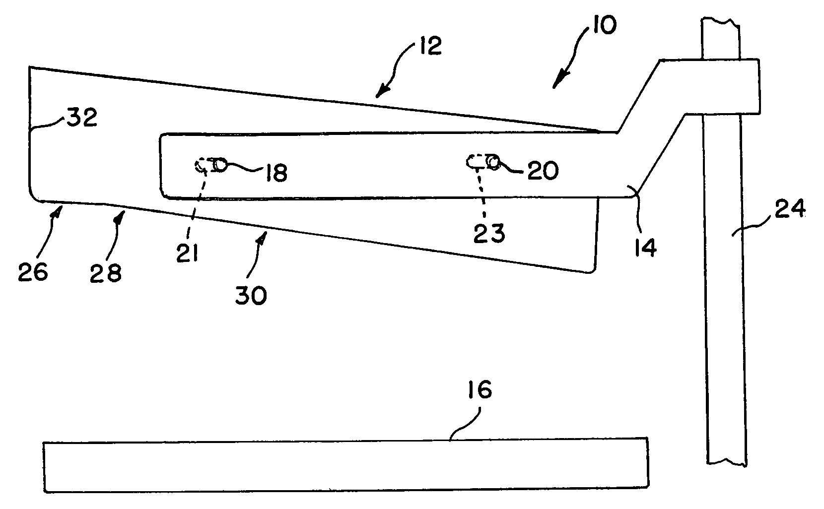
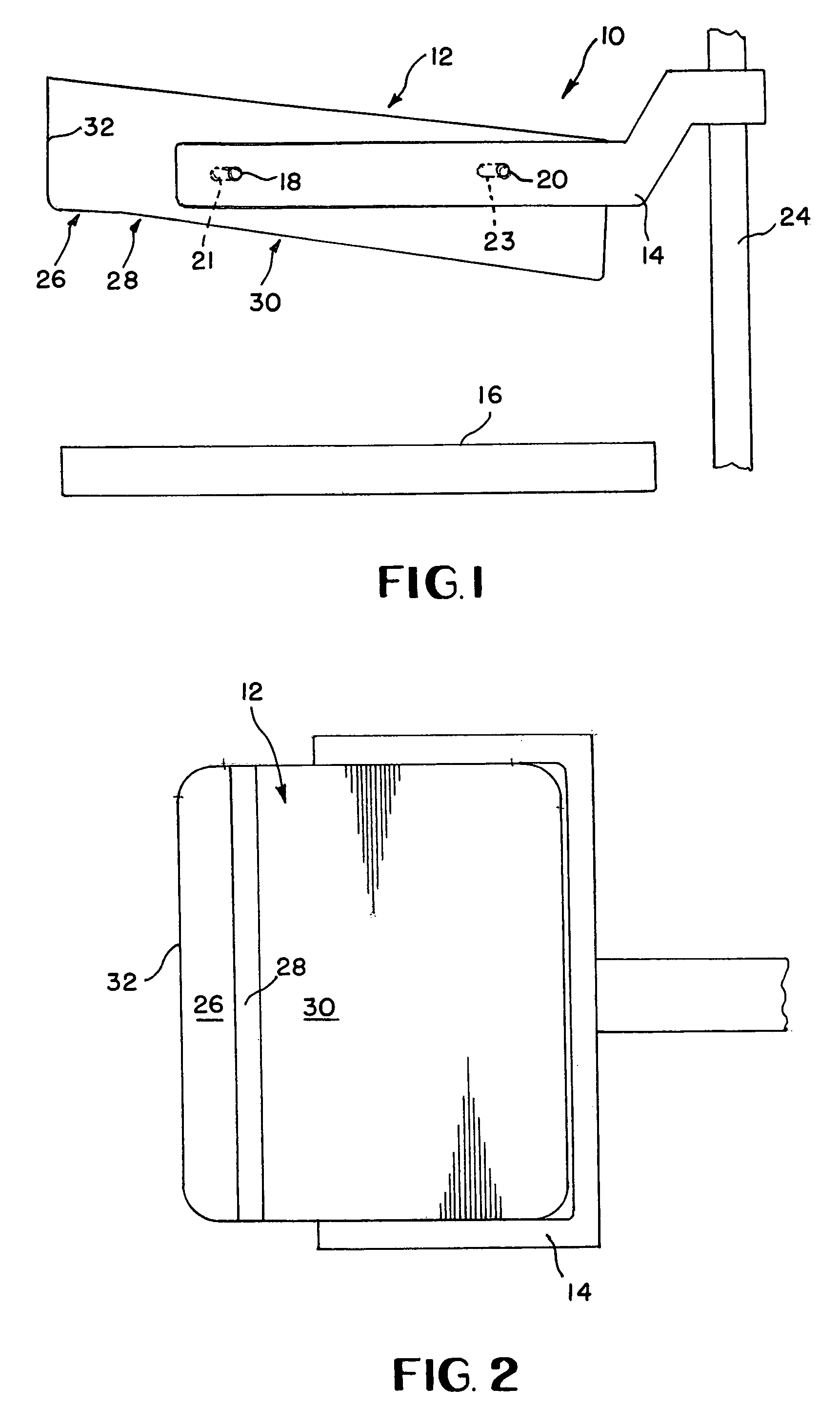
[0035]Accordingly, a compression system 10 of the preferred embodiment is illustrated in FIG. 1. The compression system includes a paddle 12 connected to a frame 14. This frame 14 is adjustable vertically relative to a support plate 16. An image detector (not shown) is typically located immediately below the support plate 16 or comprises a portion of the support plate 16. The compression system 10 shown in FIG. 1 shows a minimal number of components. Additional components known in the art and are shown in some of the references cited and are helpful in automating the compression system 10.

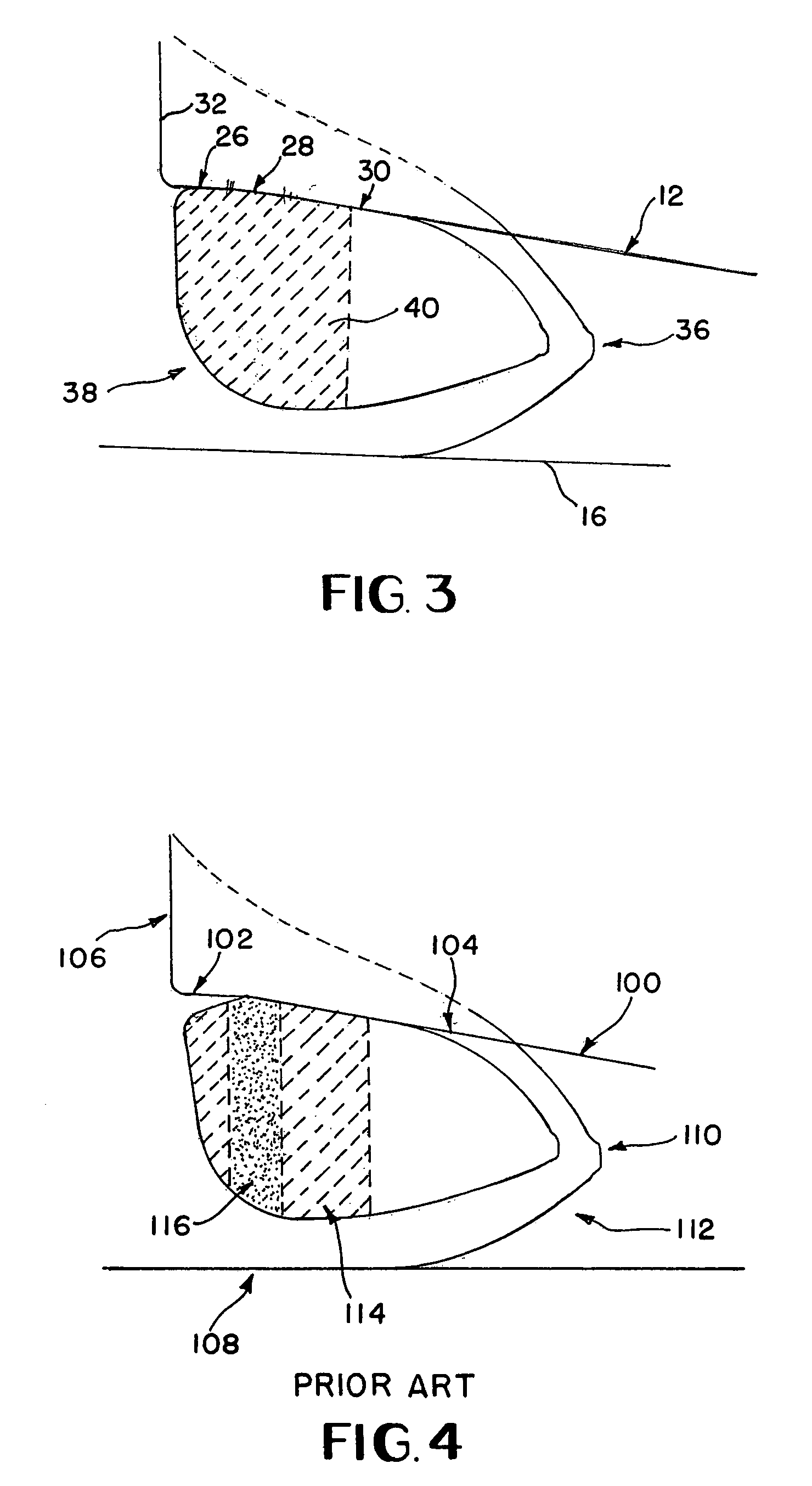
[0036]FIG. 2 shows a top view of the paddle 12. The paddle 12 is connected to frame 14. Referring back to FIG. 1, the frame 14 is also vertically adjustable relative to guide 24 to selectively adjust the vertical position of the paddle 12 relative to the support plate 16. This way a breast 36 as shown in FIG. 3 may be compressed intermediate the paddle 12 and the support plate 16.

[0037]The paddle 1...


PUM


Abstract

A breast compression device for use with a conventional mammography system is disclosed. The device comprises a paddle support frame which is slidably connected to a conventional mammography system's compression paddle carriage. A mounting arm may be provided for attaching the paddle support frame to the mammography system. The device further comprises a compression surface having a chest wall end and a nipple end. The paddle support frame is located between the x-ray tube and the detector of the mammography system. The compression surface of the device is comprised of three angled segments which conform to the normal contours of the breast.

Description

CLAIM OF PRIORITY[0001]This application claims the benefit of U.S. Provisional Patent Application No. 60 / 406,564 filed Aug. 28, 2002.BACKGROUND OF THE INVENTION[0002]1. Field of the Invention[0003]This invention relates to a mammography compression device, and more particularly to a compression paddle which provides a more uniform compression to a woman's breast while preventing too much compression at the chest wall and yet providing enough compression towards the nipple end of the breast.[0004]2. Description of Related Art[0005]Mammography systems utilize a compression paddle which is used to compress the breast of a patient intermediate a support plate and the compression paddle. Good compression of the breast is necessary for good quality mammographic images. Good compression spreads apart the breast structures which reduces superimposed structures and spreads apart the breast tissue permitting better visualization of abnormalities.[0006]Good compression of the breast improves m...

Claims


Application Information

Patent Timeline
Patent Type & Authority Patents(United States)
IPC IPC(8): A61B6/04
CPCA61B6/0414A61B6/502
Inventor HIXSON, SR., GORDON L.
Owner AMERICAN MAMMOGRAPHICS
Learn More