Coupled capillary fiber based waveguide biosensor

a biosensor and capillary fiber technology, applied in the field of waveguided biosensors, can solve the problems of inability to achieve large-scale production, limited application of optical characteristics and amenity to large-scale production, and inability to achieve irreproducible operational characteristics, etc., to achieve the effect of minimizing optical modal interferen

Inactive Publication Date: 2005-12-13
VERIDIAN SYST DIV
View PDF28 Cites 27 Cited by
  • Summary
  • Abstract
  • Description
  • Claims
  • Application Information

AI Technical Summary

Benefits of technology

[0013]An advantage of the arrangement is that in addition to light intensity or magnitude comparisons, the light conducted by one or both of the capillary and optical fiber may assume different optical polarities, enabling at least the second optical detector to sense a change in the optical polarity for analysis purposes. In the preferred embodiment the light traveling through the fiber and capillary are single mode. This minimizes optical modal interferences. In addition, the light conducted by the capillary is many applications is able to propagate in multiple optical modes, with the presence / absence of the constituent binding event still being determinative of the changes of localized refractive index within the evanescent field.

Problems solved by technology

But since there is little or no absorption or other phenomena to alter the amount of the light carried by the fiber, no attenuation or detectable characteristics are developed.
Though versatile for some applications, the apparatus just described is limited in terms of applicable optical characteristics as well as amenability to large-scale production.
Difficulties in construction lead to poor, irreproducible operational characteristics.

Method used


Image

  • Coupled capillary fiber based waveguide biosensor
  • Coupled capillary fiber based waveguide biosensor
  • Coupled capillary fiber based waveguide biosensor

Examples


Embodiment Construction

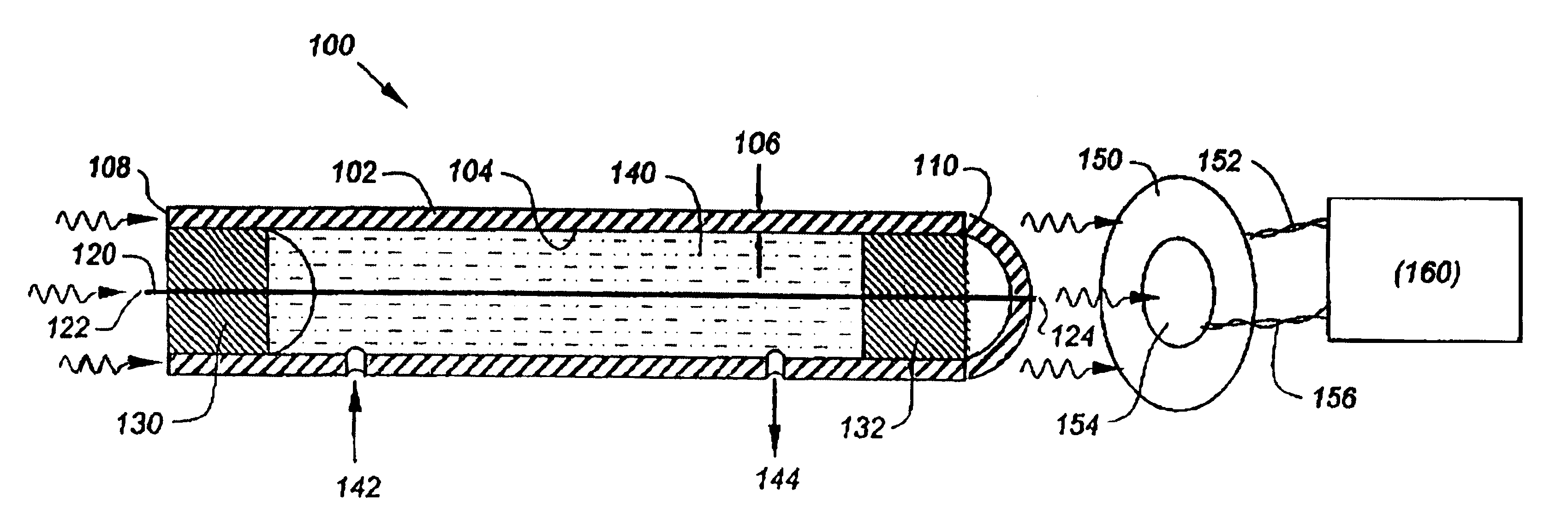
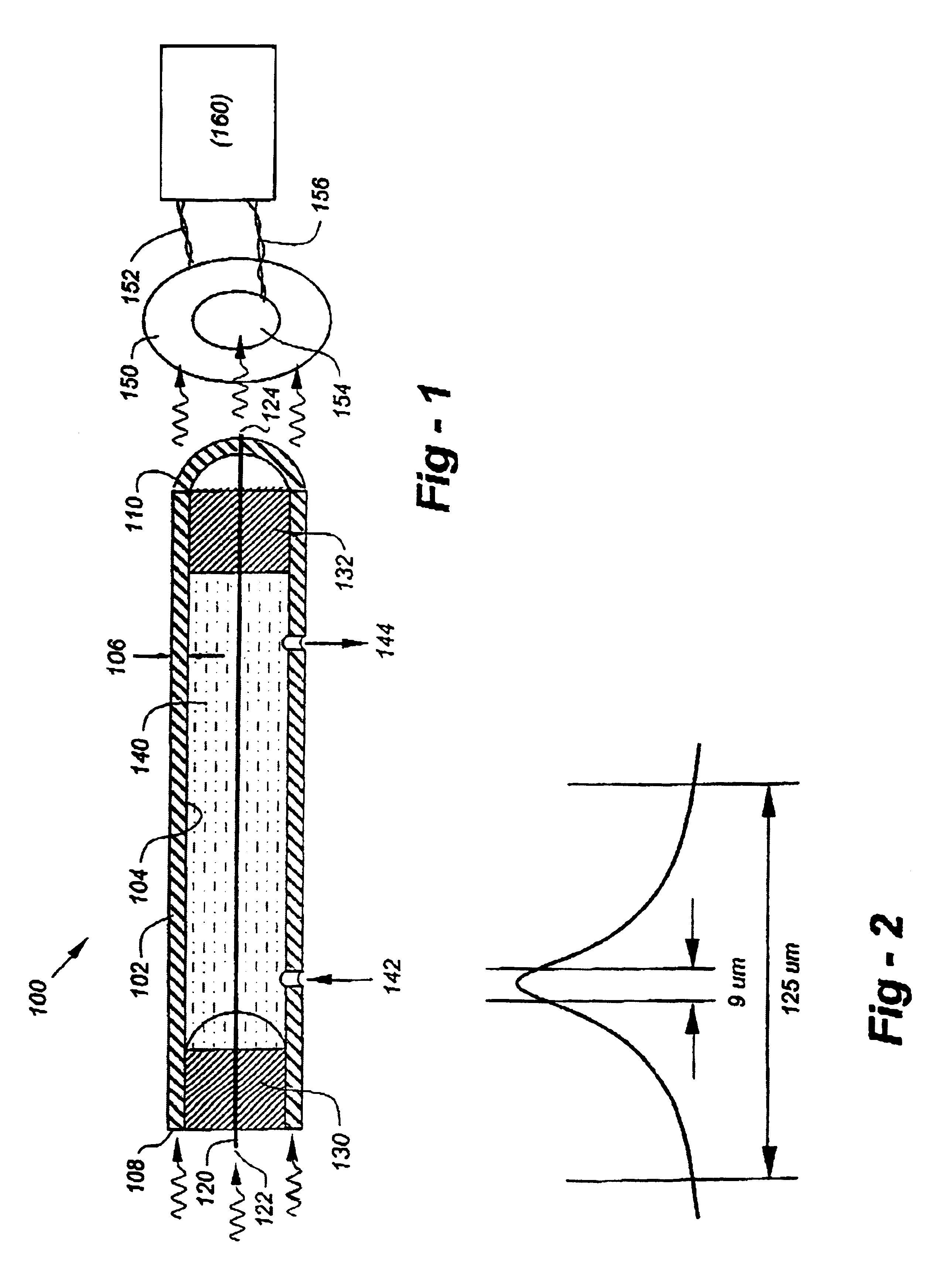
[0029]Reference is now made to FIG. 1, which is a drawing used to illustrate important structures and functional operation according to the invention. The basic configuration, shown generally at 100, includes an optically conductive hollow waveguide 102 and a second waveguide 120 supported therewithin. The hollow waveguide 102 has a light-input end 108, and a light-output end 110, and a wall having a thickness 106 and an inner surface 104. Likewise, the second waveguide 120, features a light-input end 122, a light-output end 124, and an outer surface generally facing the inner surface 104 of the hollow waveguide 102.

[0030]In the preferred embodiment, the hollow waveguide 102 is a glass capillary, and the second waveguide 120 is an optical fiber. Conveniently, the waveguide 120 may be held in position using ferrules 130 and 132 which seal against the inner wall 104 of the waveguide 102, and have central apertures through which the waveguide 120 may be threaded. Preferably, the wavegu...


PUM

PropertyMeasurementUnit
wall thicknessesaaaaaaaaaa
outer diameteraaaaaaaaaa
thicknessaaaaaaaaaa

Abstract

An evanescent-wave optical biosensor includes a hollow optical waveguide, preferably in the form of a light-conductive capillary, surrounding a central waveguide preferably in the form of an optical fiber to create a sealed cavity. A source of optical energy as from a laser is directed into one or both of the light-input ends of the capillary and fiber, such that an evanescent field extends into the cavity from one or both of the inner surface of the capillary and the outer surface of the fiber. A first biomolecular constituent is attached to one or both of the inner wall of the hollow optical waveguide and the outer surface of the second optical waveguide, such that the first biomolecular binding partner is substantially within the evanescent field if present. A first optoelectric detector is supported to receive light from the light-output end of the capillary and convert the light received into a first electrical signal, and a second optoelectric detector is supported to receive light from the light-output end of the fiber and convert the light received into a second electrical signal. A fluid within the cavity which may contain a second biomolecular constituent having a binding affinity to the first biomolecular constituent, such that if binding occurs between the biomolecular constituents, a representative change occurs in the light emerging from one or both of the output ends of the hollow and second optical waveguides and the electrical signals from the optoelectric detectors.

Description

FIELD OF THE INVENTION[0001]This invention relates generally to waveguided biosensors and, in particular, to a sensor that utilizes a parallel optical fiber / capillary combination to achieve a sensor configuration with enhanced capabilities.BACKGROUND OF THE INVENTION[0002]Optical fibers are being used in a variety of biosensor applications. For example, as discussed in U.S. Pat. No. 5,494,798, a fused biconical fiber optic fiber coupler may be used without cladding to exploit the evanescent field present immediately outside the fiber / air interface in its “waist” region. If an antibody is bound to the exposed surface of the bare waist region of the fiber optic coupler, the evanescent field envelopes the molecule. But since there is little or no absorption or other phenomena to alter the amount of the light carried by the fiber, no attenuation or detectable characteristics are developed.[0003]However, when the antibody's target antigen binds to the antibody, the localized changes in r...

Claims


Application Information

Patent Timeline
Patent Type & Authority Patents(United States)
IPC IPC(8): G01N33/543
CPCG01N21/7703G01N33/54373
Inventor LOCKHART, MICHAEL D.
Owner VERIDIAN SYST DIV
Why Eureka
Try Eureka