Rotating and pivoting magnet for magnetic navigation

a rotating and rotating magnet technology, applied in the field of magnetic navigation, can solve the problems of large exclusion zones, difficult to construct permanent magnets, and high construction costs, and achieve the effect of sufficient strength

Inactive Publication Date: 2005-12-13
STEREOTAXIS
View PDF9 Cites 160 Cited by
  • Summary
  • Abstract
  • Description
  • Claims
  • Application Information

AI Technical Summary

Benefits of technology

[0005]The present invention relates to a magnet, and to a magnet system that is capable of generating useful magnet fields in virtually any direction, at distances from the magnet sufficient to conduct medical procedures in the patient's body. The magnet is designed so that a magnetic field can be generated in virtually any direction with a minimum amount of movement so that the exclusion zone—the zone from which the patient and other medical equipment and personnel cannot be located—or the inclusion zone—the zone that the magnet occupies—is minimized.
[0006]Generally the magnet of the present invention com

Problems solved by technology

Electromagnets and in particular superconducting electromagnets can create strong magnet fields and gradients, but they are expensive to construct and operate.
Until recently, it was difficult to construct a permanent magnet that could provide a sufficiently strong and universally directed magnetic field and gradient at a distance su

Method used


Image

  • Rotating and pivoting magnet for magnetic navigation
  • Rotating and pivoting magnet for magnetic navigation
  • Rotating and pivoting magnet for magnetic navigation

Examples


Embodiment Construction

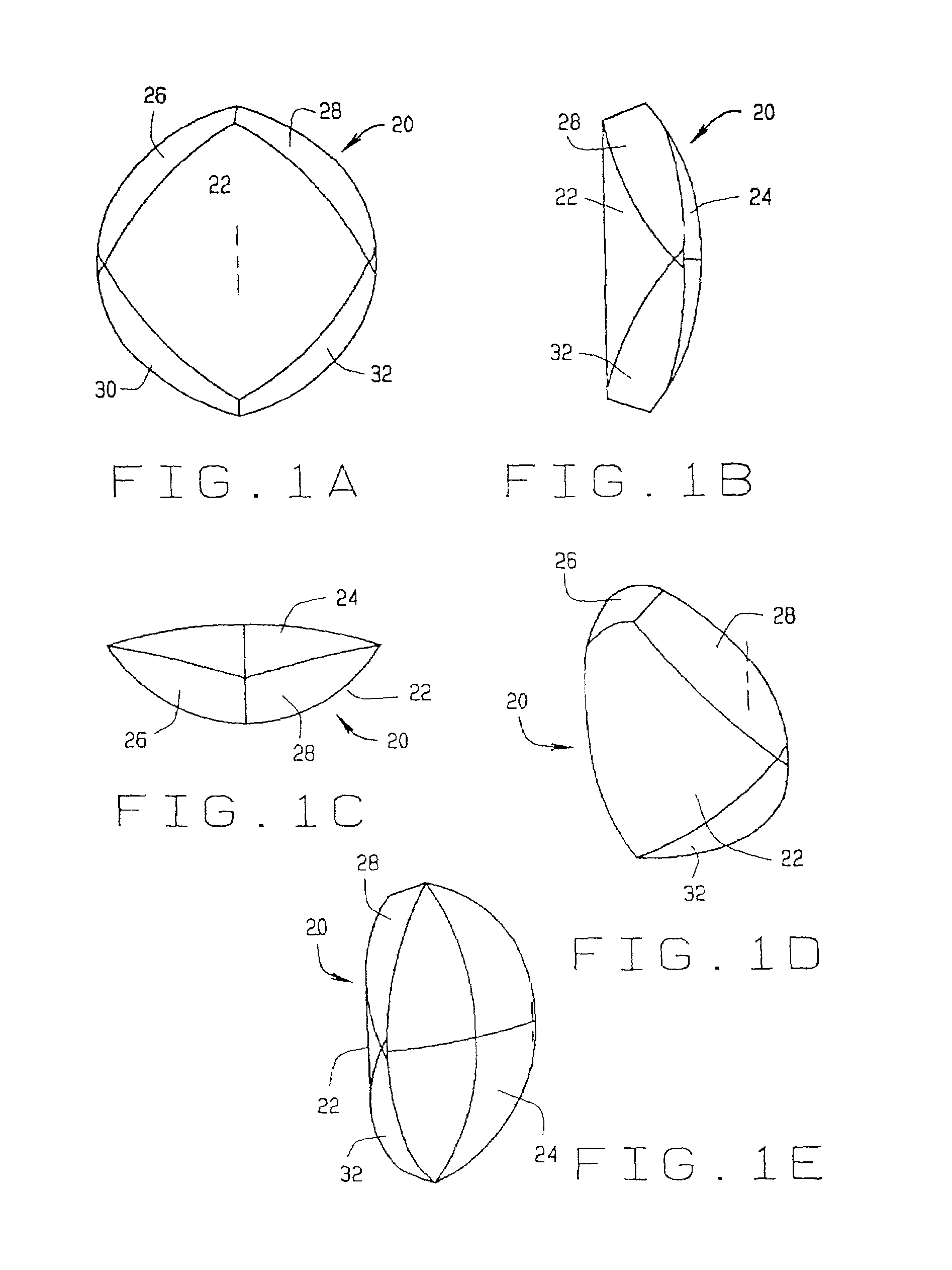
[0035]A magnet constructed according to the principles of this invention is indicated generally as 20 in FIGS. 1A through 1E. The magnet 20 comprises a generally cylindrical front face 22 and a back face 24. There are left top face 26 and a right top face 28, and a left bottom face 30 and a right bottom face 32. The magnet 20 preferably comprises a plurality of parallel bands or segments of permanent magnetic material extending from top to bottom. The magnetization direction of each segment is preferably selected to generally optimize the magnet field at a magnet operating point spaced from the center of the front face of the magnet. This magnet operating point is a design criteria of the magnet. For applications where a magnet field is to be applied relatively close to the magnet, such a neurology applications, the magnet operating point may be selected closer to the surface of the magnet, for applications where a magnetic field is to be applied relatively far from the magnet, such...


PUM


Abstract

A magnet assembly comprising a magnet mounted for pivoting about a first axis spaced from the magnet, and rotating about a second axis that is perpendicular to and intersects with the first axis. The magnet comprising a plurality of segments each with a magnetization direction such that through a combination of pivoting and rotating the magnet projects a magnetic field in any direction at an operating point spaced from the front of the assembly. The segmented construction with segments of different magnetization directions allows small changes in the orientation of the magnet to substantially change the magnet field direction at a system operating point.

Description

FIELD OF THE INVENTION[0001]This invention relates to magnet medical procedures, and in particular to a magnet useful in navigating magnetic medical devices in the body.BACKGROUND OF THE INVENTION[0002]Electromagnets and permanent magnets have been developed for moving magnet medical devices in the body. Some magnets used in medical applications apply a gradient to pull magnet medical devices within the body. Other magnets used in medical applications simply apply a magnetic field in a selected direction to align magnetic medical devices in the selected direction. Still other magnets apply both a magnetic field and a magnetic gradient to simultaneously orient and move a magnetic medical device.[0003]There are a number of important competing design considerations for magnets used in medical procedures. First and foremost is providing sufficient field strength or gradient to orient or move the magnetic device. Electromagnets and in particular superconducting electromagnets can create ...

Claims


Application Information

Patent Timeline
IPC IPC(8): A61B6/12A61B19/00H01F7/02
CPCA61B19/22H01F7/0278A61B6/12A61B2019/2253A61B2019/2265A61B34/70A61B34/73A61B2034/733
Inventor CREIGHTON, IV, FRANCIS M.
Owner STEREOTAXIS
Why Eureka
Try Eureka