Wastegate for a turbocharged internal combustion engine

a wastegate valve and internal combustion engine technology, which is applied in the direction of combustion engines, valve arrangements, machines/engines, etc., can solve the problems of limiting the maximum rotational speed of the turbine wheel and the maximum pressure of the charge air supplied to the engine, introducing further complexity, cost and durability concerns into the design of the turbocharger, and increasing the cos

Inactive Publication Date: 2005-12-20
TURBONETICS HLDG
View PDF10 Cites 44 Cited by
  • Summary
  • Abstract
  • Description
  • Claims
  • Application Information

AI Technical Summary

Benefits of technology

[0009]The present invention provides a remote wastegate valve for use with a turbocharger and an internal combustion engine. An exemplary remote wastegate valve provided by the present invention has a swing gate pivotally mounted to move between an open position that allows the flow of exhaust gases through the wastegate and a closed position that blocks passage of the exhaust gases therethrough. In the open position, a recess in the passage through the housing of the wastegate receives at least a part of the swing gate to maintain a constant cross-sectional area throughout the passage so that the flow of exhaust gases through the wastegate valve may be free and unencumbered.
[0011]In contrast to a wastegate that is integral to a turbine housing, the remote wastegate advantageously can be removed and replaced without removing the turbocharger, can be disassembled which makes repairs easier, its performance can be adjusted easily, and generally a remote wastegate generally is more sensitive to “controlling” signals.

Problems solved by technology

Consequently, controlled operation of the wastegate limits the maximum rotational speed of the turbine wheel and the maximum pressure of the charge air supplied to the engine.
Forming an integral wastegate valve in the turbine housing introduces further complexity, cost and durability concerns into the design of the turbocharger.
Part of the cost increase comes from the need to analyze the effect of the flow of exhaust gases through the bypass when the wastegate valve is open as well as the effect on the flow of exhaust gases when the wastegate is closed.
Retrofitting an existing turbocharger to include an internal wastegate generally is impractical or impossible.
Unfortunately, even in the open position these valves remain in the path of the exhaust gas flow and hinder the flow of exhaust gases through the wastegate valve, thus reducing engine efficiency.

Method used


Image

  • Wastegate for a turbocharged internal combustion engine
  • Wastegate for a turbocharged internal combustion engine
  • Wastegate for a turbocharged internal combustion engine

Examples


Embodiment Construction

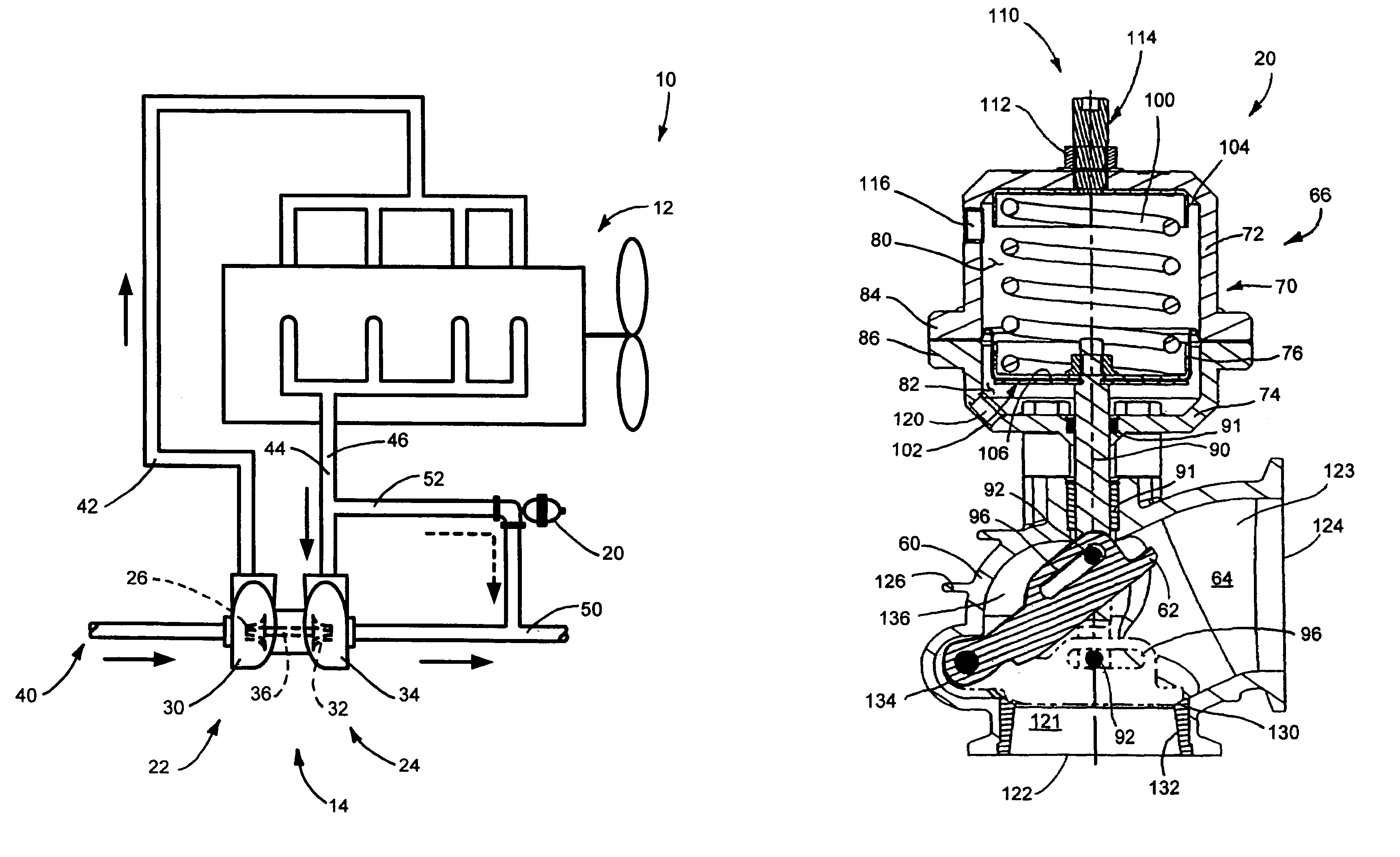
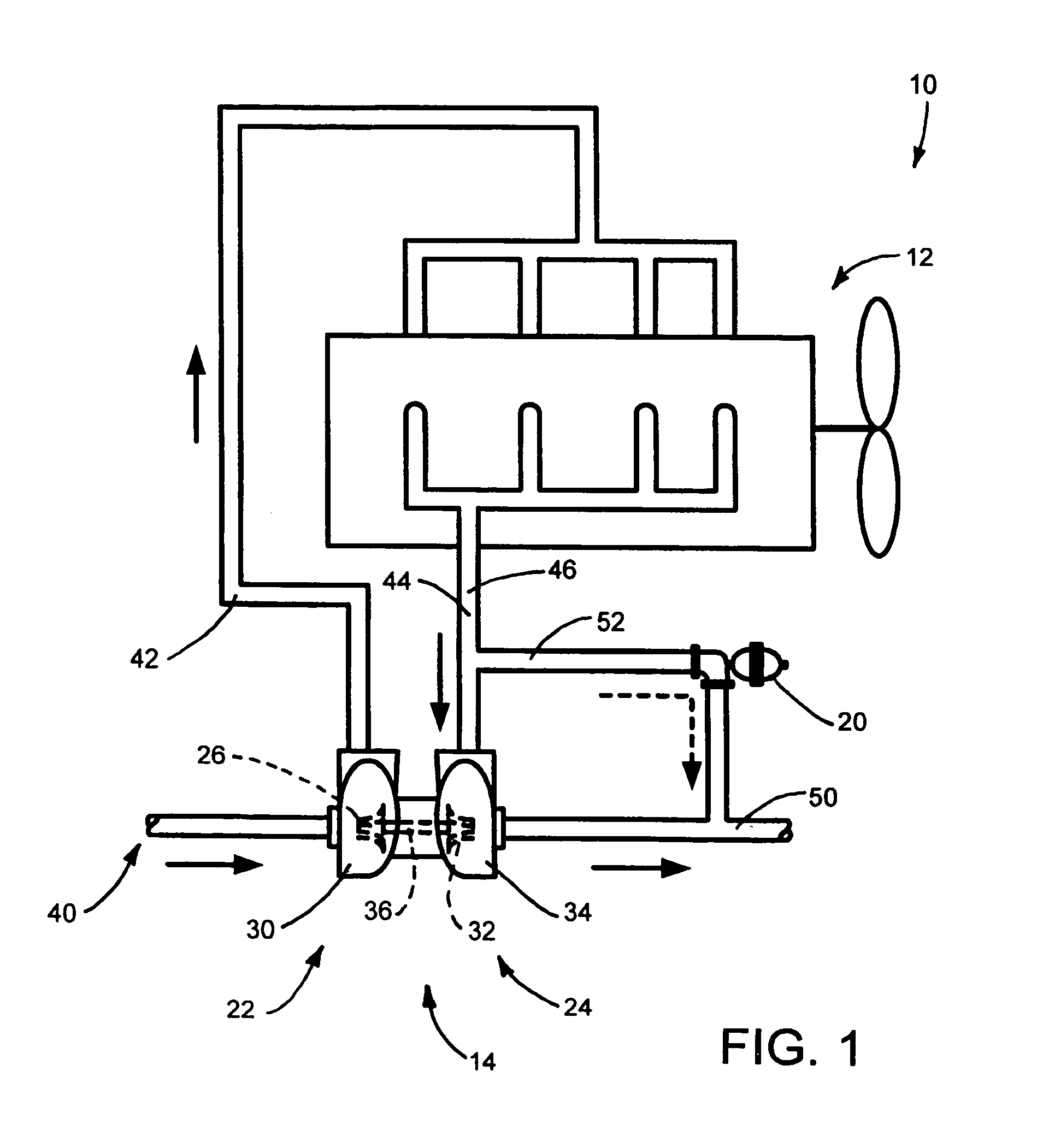
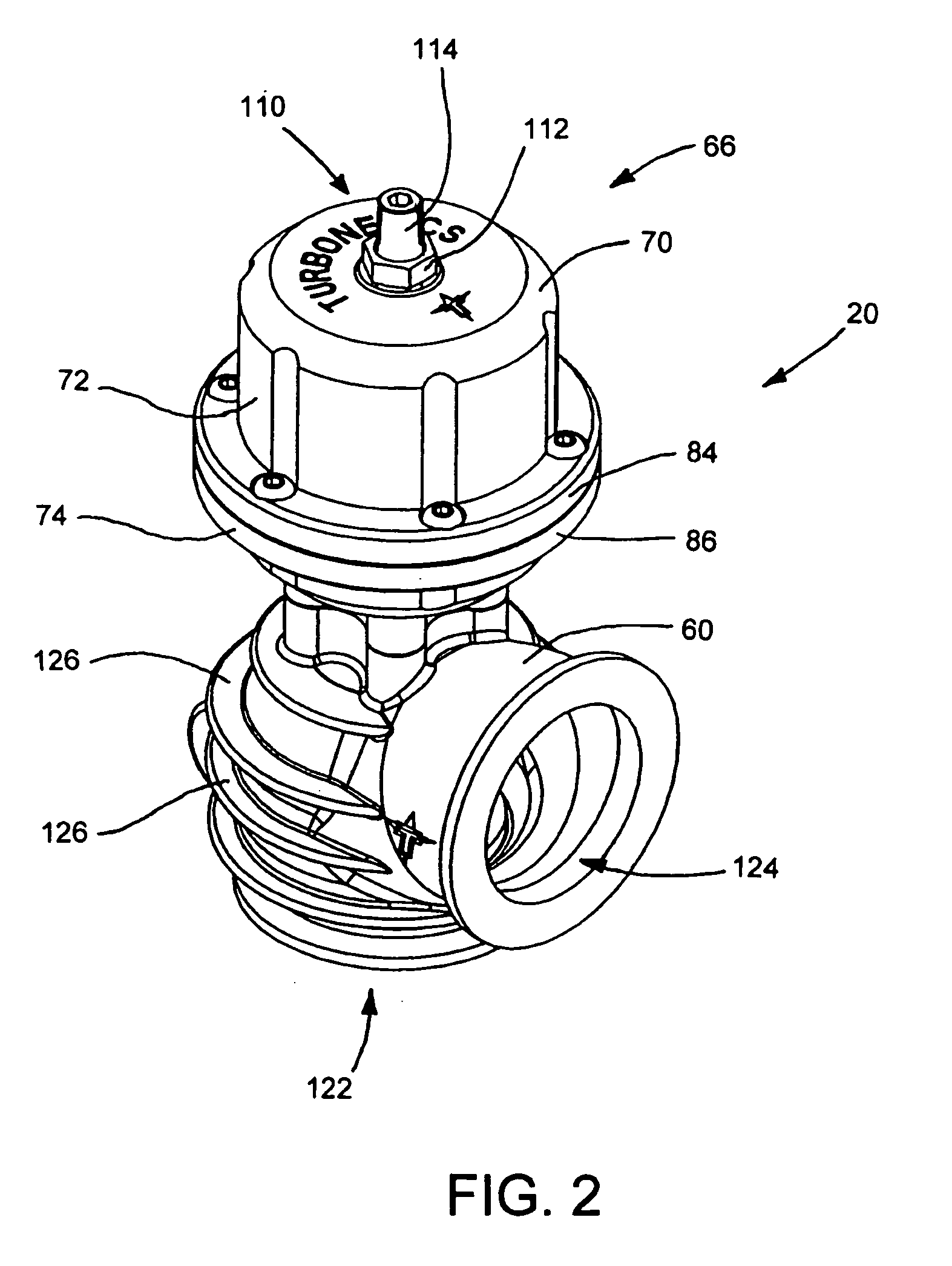
[0017]The present invention provides a turbocharged internal combustion engine system 10 as shown in FIG. 1. The system 10 generally includes an internal combustion engine 12 such as a gasoline-powered engine or a diesel-powered engine having one or more combustion cylinders (not shown), one or more turbochargers 14 and one or more improved remote wastegate valves or wastegates 20. Respective sections of conduit interconnect the components of the system.

[0018]The turbocharger 14 includes a compressor 22 and a turbine 24. The compressor 22 includes a compressor wheel 26 in a compressor housing 30, and the turbine 24 includes a turbine wheel 32 in a turbine housing 34. A common shaft 36 connects the compressor wheel 26 to the turbine wheel 32 for mutual rotation. The compressor wheel 26 compresses air for combustion in the engine 12 and the turbine wheel 32 drives the compressor wheel 26 using exhaust gases from the combustion in the engine 12.

[0019]In operation, ambient air drawn thr...


PUM


Abstract

A wastegate valve for a turbocharger that is separate from the turbocharger has an actuator mounted to a valve housing. The valve housing has a passage therethrough and a swing valve that opens and closes the passage. The swing valve has a pivot point that lies outside the path of the exhaust gases. The passage has a recess therein that receives a portion of the swing valve in its open position to improve the flow of exhaust gases through the passage. In an internal combustion engine system, the wastegate valve forms part of a bypass conduit that redirects a portion of the exhaust gases from an engine away from and past the turbocharger.

Description

FIELD OF THE INVENTION[0001]The present invention relates to turbochargers that supply relatively high pressure charge air to the intake of an internal combustion engine. More particularly, the present invention relates to a remote wastegate valve for a turbocharged internal combustion engine.BACKGROUND OF THE INVENTION[0002]Turbochargers enable the delivery of higher density fuel-air mixtures to one or more combustion chambers or cylinders of an engine in comparison to conventional naturally aspirated engines. An increase in the density of the fuel-air mixture generally improves engine performance and efficiency.[0003]A turbocharger typically includes a turbine wheel and a compressor wheel connected to a common shaft and supported in respective housings (the respective wheels, housings and associated components generally are referred to collectively as the “turbine” and the “compressor”, respectively). The turbine housing includes an exhaust gas inlet and outlet. The inlet couples ...

Claims


Application Information

Patent Timeline
Patent Type & Authority Patents(United States)
IPC IPC(8): F02B37/18
CPCF02B37/183F02B37/186Y02T10/144Y02T10/12
Inventor HASTINGS, MICHAL AARONLEWIS, BRADLEY DEAN
Owner TURBONETICS HLDG
Why Eureka
Try Eureka