
Method and apparatus for controlling refrigeration

Inactive Publication Date: 2005-12-20
UNIVERSAL MASTER PRODS
View PDF17 Cites 36 Cited by
  • Summary
  • Abstract
  • Description
  • Claims
  • Application Information

AI Technical Summary

Benefits of technology

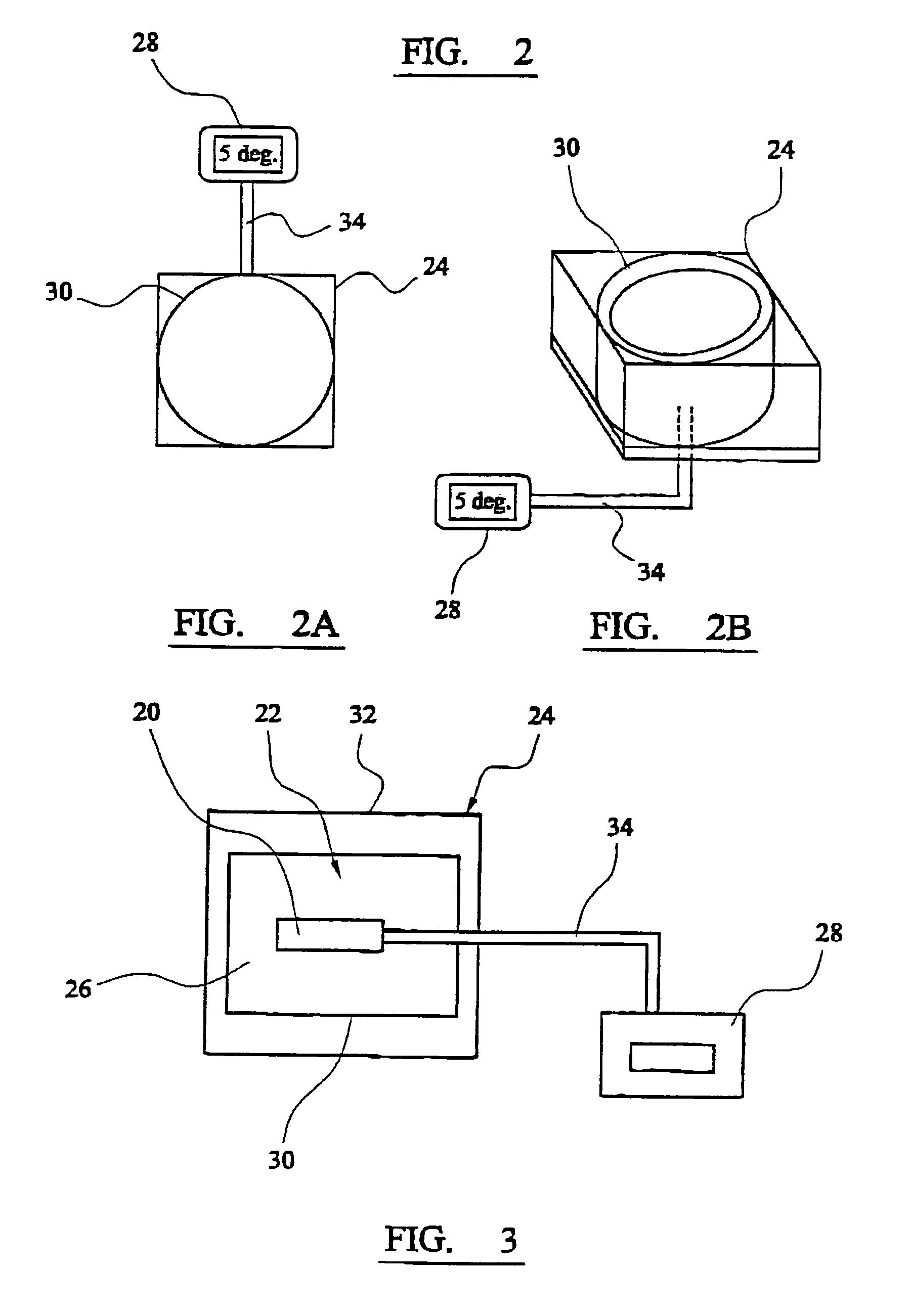
[0009]In accordance with the principles of our discovery, the proper basis for evaluating the only temperature of interest within a refrigerator (namely the temperature of the food therein enclosed) is to, in essence, sample the food temperature therein. Now, while invasive food temperature sampling by use of inserted probes and the like is fraught with practical difficulties and liberally fenced-around with food hygiene regulations, (so that actual food internal temperature sensing becomes a practical impossibility), we have discovered that there is a practical alternative approach which is not foreshadowed in the prior art, and in accordance with this principle the proper approach to the sensing of such temperatures is by internal sensing within a simulated body of food. Thus, in accordance with this approach, the method and apparatus of the invention provides the means whereby temperature can effectively be sensed from within food stored within the refrigerator, or in the case of a heating system (such as a microwave oven) from within food being heated in such a heating appliance.

Problems solved by technology

This latter factor is of great relevance, we have discovered, since although (as the prior art teaches) the air temperature within a refrigerator or deep freeze rises rapidly when the door is opened, the actual effect of the air temperature on the stored food is often quite marginal and there can be a temperature difference between the air and the stored food of 10° C. or more while an unmodified air temperature sensing system in a refrigerator (as is conventionally provided in domestic appliances) will react relatively wildly to such fluctuations, and such is obviously undesirable for energy conservation reasons.
Equally there is the converse situation where the approach has been taken that such over-reaction of the temperature control system is ineffective and wasteful, but it is equally true that mere damping of the system is not the effective answer either because damping merely lowers the amplitude of the reactive peaks of the system without addressing the underlying problem or question.

Method used


Image

  • Method and apparatus for controlling refrigeration
  • Method and apparatus for controlling refrigeration
  • Method and apparatus for controlling refrigeration

Examples


Embodiment Construction

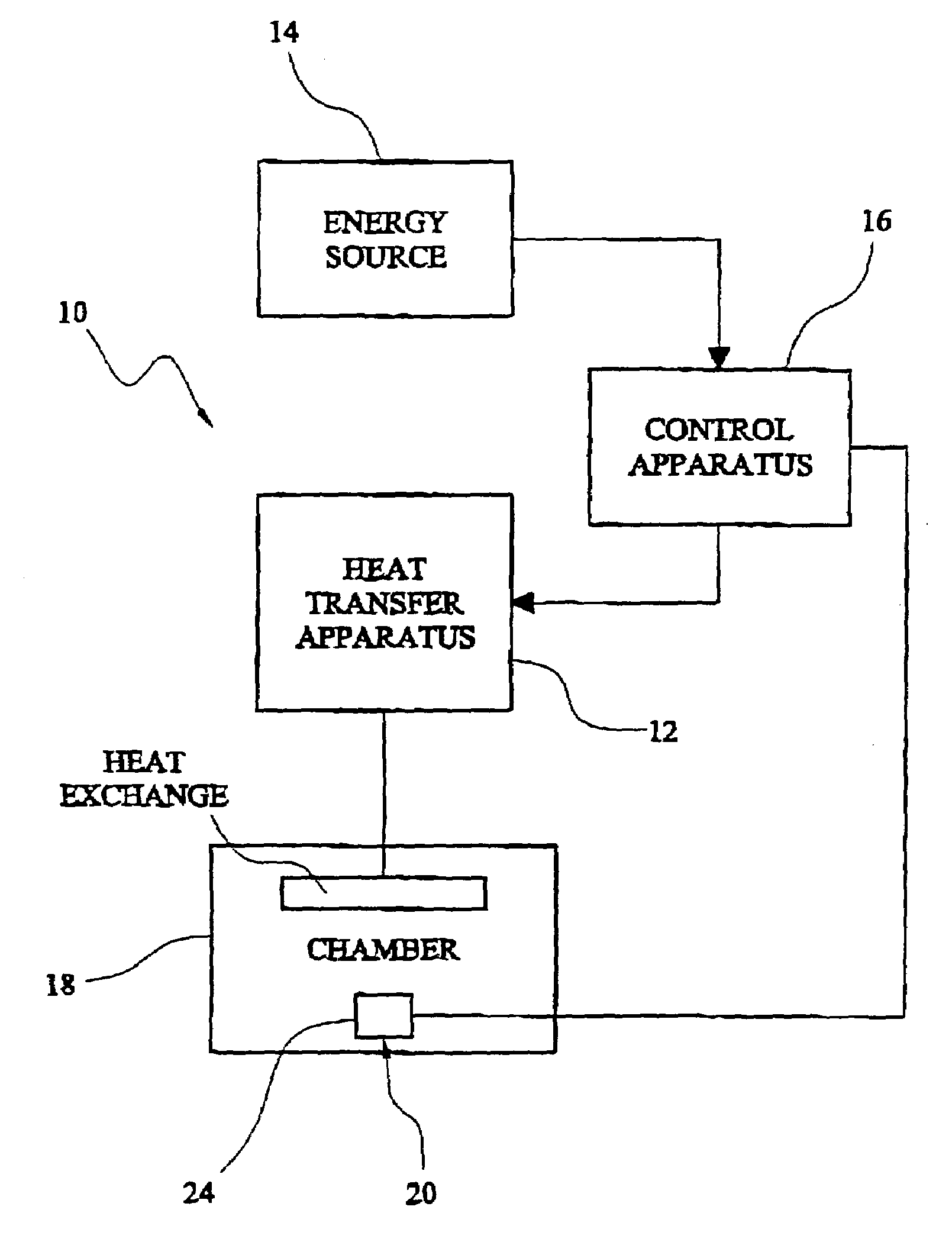
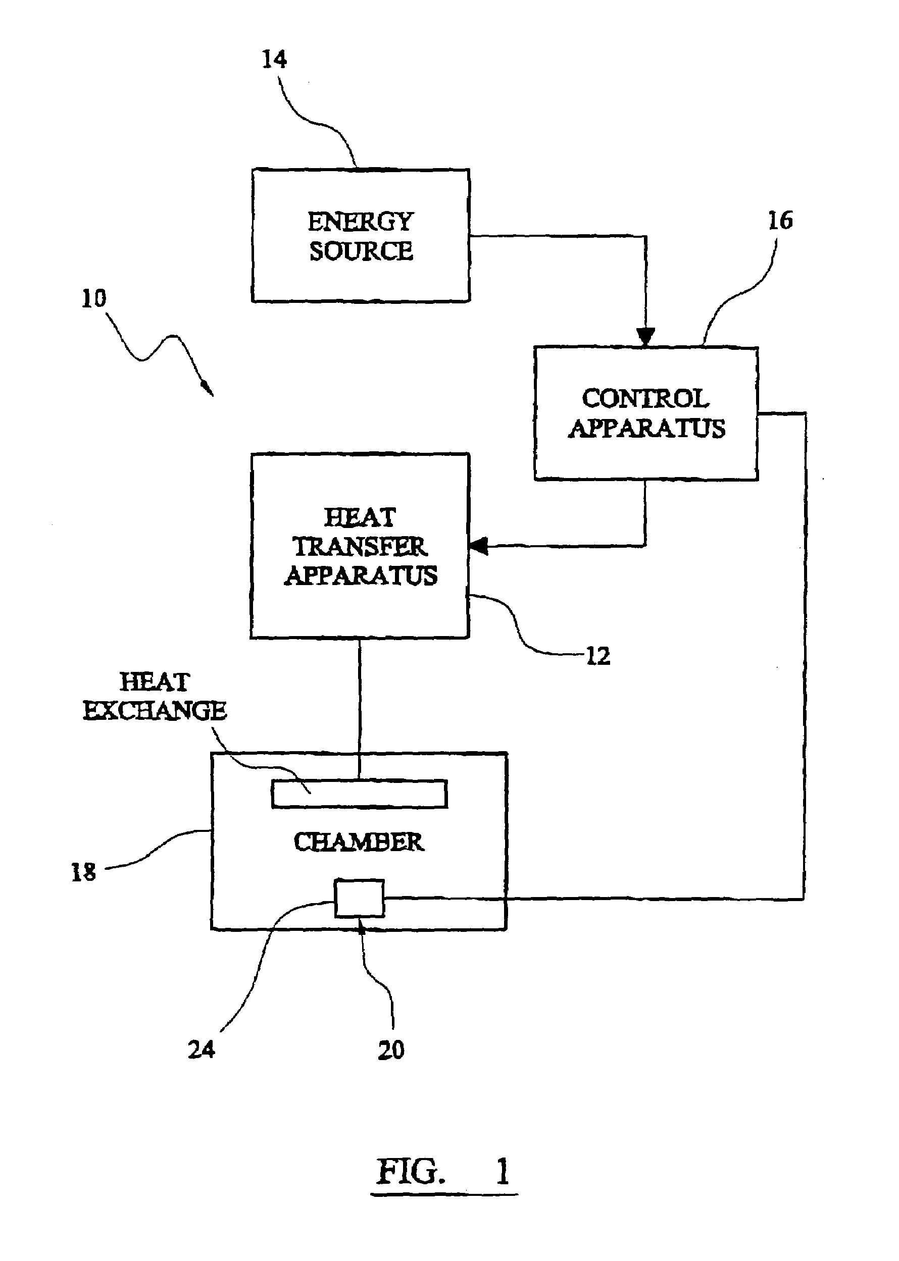
[0057]As shown in FIG. 1 apparatus 10 for controlling article heat transfer apparatus 12 connectable to an energy source 14 comprises control apparatus 16 to control the operation of the heat transfer apparatus 12 in accordance with sensed thermal characteristics.

[0058]A chamber 18 is provided to contain one or more of the articles (not shown) to or from which heat transfer is to be effected, during operation of the heat transfer apparatus.

[0059]Chamber 18 is in operative association with the heat transfer apparatus 12 so that the latter can cause heat transfer to or from the chamber and hence to or from articles contained therein.

[0060]Control apparatus 16 comprises a thermal sensor 20 responsive to sensed thermal characteristics within the chamber.

[0061]Control apparatus 16 further comprises a thermal sink or body 22 associated with sensor 20 and having a thermal capacity to modify the responsiveness of control apparatus 16 to thermal characteristics within chamber 18.

[0062]In acc...


PUM


Abstract

A thermal sensor (20) located in the centre of a food simulant composition (24) linked to a remote measuring indicating and / or regulating device (28). The temperature of the food simulant changes in the same way as food stored in its vicinity and is unaffected by the movement of the ambient air which varies in temperature dramatically. This allows an actual reading and recording of stored food temperature and the regulation of the temperature within a refrigerated space by a thermostat (16). Its uses are mainly for frozen, chilled and refrigerated food, and the reading of temperature of food cooked for example in micro-wave ovens.

Description

BACKGROUND OF THE INVENTION[0001]This invention relates to a method and apparatus for controlling refrigeration apparatus. An example of the application of the invention is to a method and apparatus for controlling the operation of domestic and commercial food storage refrigeration apparatus including deep freeze apparatus. However, the invention also provides, as such, the apparatus which operates in accordance with the aforesaid method for controlling such refrigeration apparatus, and provides temperature sensing apparatus.[0002]Further aspects of the invention relate to the use of the method and apparatus for the control of apparatus for raising the temperature of food and the like, for example microwave cooking apparatus. Further aspects of the invention relate to a method and apparatus for conducting thermal tests and calibration in relation to refrigeration and heating apparatus.[0003]There is disclosed in WO 94 / 10546 (reference P51957WO) a method and apparatus applicable to t...

Claims


Application Information

Patent Timeline
IPC IPC(8): F24C7/02F25D11/00F24C7/04F25D29/00G01K13/00G05D23/19
CPCF25D29/00G05D23/19G01K13/00F25D2700/16G01K2007/422
Inventor LAMSTAES, ANDRELAMSTAES, GUYBANHAM, HARRY
Owner UNIVERSAL MASTER PRODS
Learn More