Offset rotary joint unit equipped with rotation correction mechanism

a technology of rotation correction mechanism and offset rotary joint, which is applied in the direction of joints, manipulators, manufacturing tools, etc., can solve the problems of difficult miniaturization of combination joints of offset rotary joint mechanism and rotation correction mechanism, minute motion delay, and difficult to achieve bending accuracy, etc., to achieve miniaturization of combination joints, eliminate power line or signal line twisting, and facilitate control

Inactive Publication Date: 2005-12-20
JAPAN AEROSPACE EXPLORATION AGENCY
View PDF10 Cites 13 Cited by
  • Summary
  • Abstract
  • Description
  • Claims
  • Application Information

AI Technical Summary

Benefits of technology

[0010]The advantage of driving the rotation correction joint mechanism and the offset rotary joint mechanism with the same drive source via a two-shaft reversal mechanism is that the control is facilitated, a minute motion delay is eliminated, and the combination joint can be miniaturized. Reverse rotation of the rotation correction joint mechanism, following the rotation of the offset rotary joint mechanism, allows the second arm to execute a two-dimensional bending motion with respect to the first arm only by virtue of a rotary mechanism. It is preferred that the first arm, rotation correction arm, and second arm are formed as hollow cylindrical bodies and that joint control units such as a motor, an angle encoder, a motor control circuit, a communication circuit, and the like be integrally housed inside the hollow cylindrical bodies. It is also preferred that through holes be provided in the rotation correction joint mechanism and the offset rotary joint mechanism, and signal lines and the like be passed therethrough. Furthermore, providing a slip ring for transmitting power and signals between the rotary bodies on a through shaft o...

Problems solved by technology

However, since each of the joint mechanisms required an independent rotation control, when the offset rotary joint mechanism and rotation correction mechanism were implemented as a pair of joint units, th...

Method used


Image

  • Offset rotary joint unit equipped with rotation correction mechanism
  • Offset rotary joint unit equipped with rotation correction mechanism
  • Offset rotary joint unit equipped with rotation correction mechanism

Examples


Embodiment Construction

[0018]The preferred embodiments of the present invention will be described below in greater detail with reference to the appended figures.

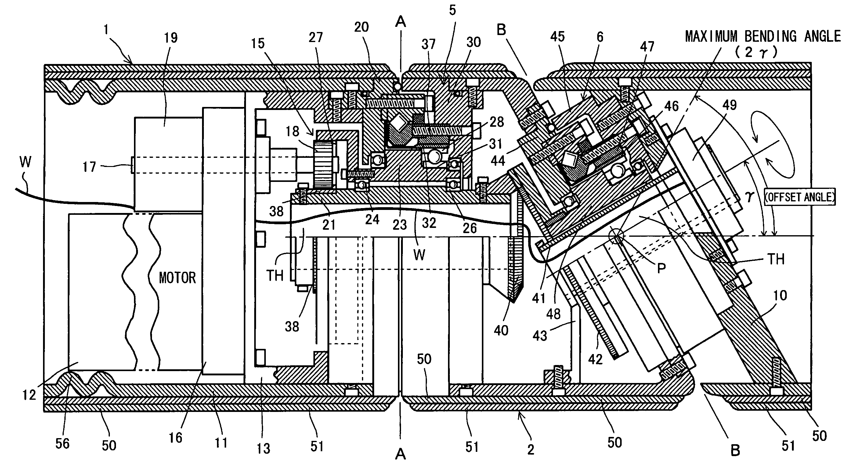
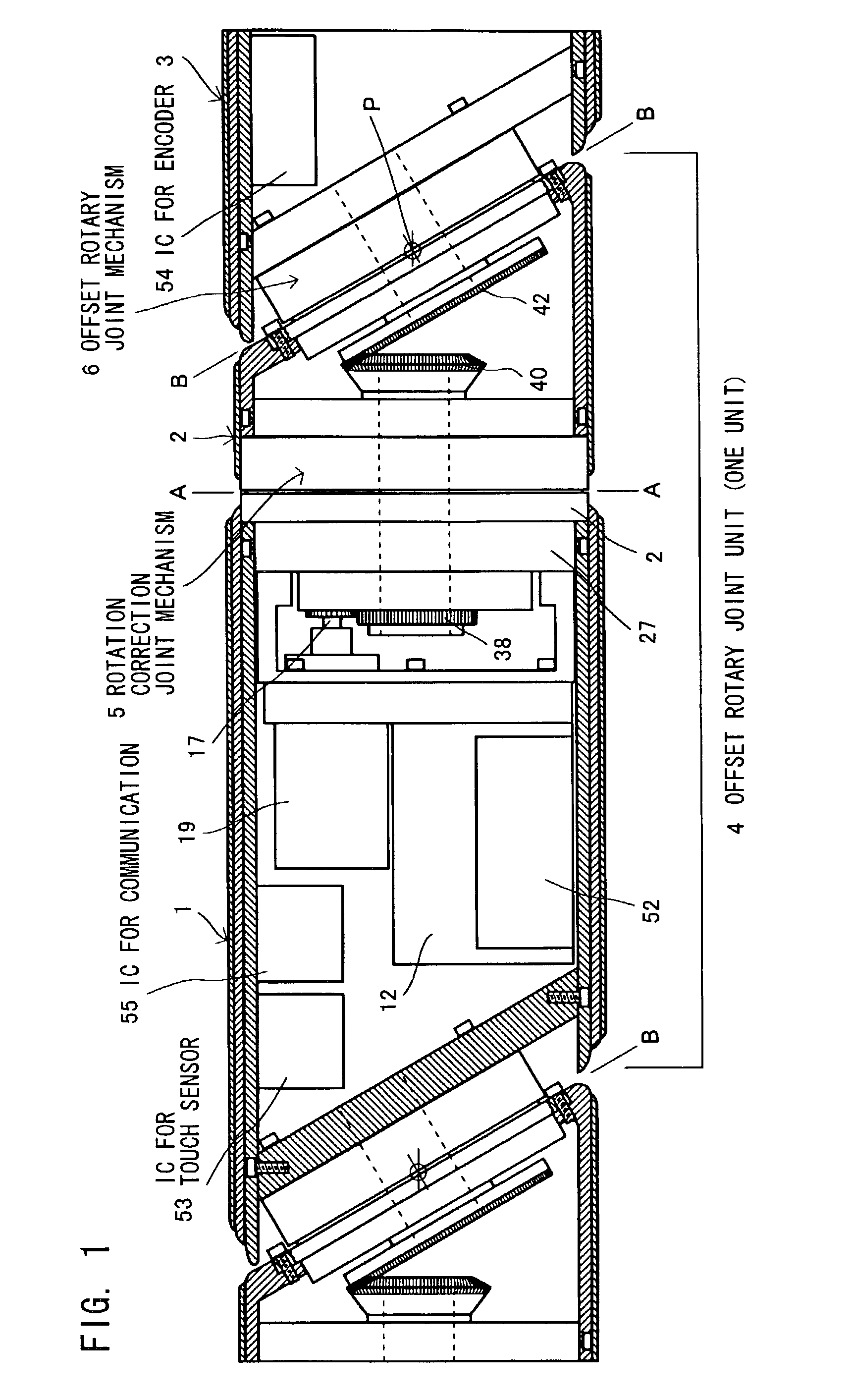
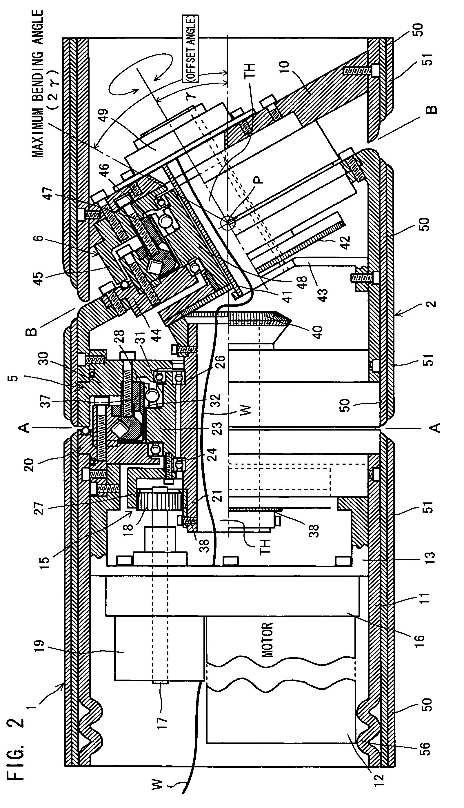
[0019]FIG. 1 schematically illustrates an embodiment of an offset rotary joint unit in accordance with the present invention. FIG. 2 is a detailed cross-sectional view thereof. FIG. 3 is a diagram which illustrates the operation thereof.

[0020]The figures show a single-joint unit of a multi-joint robot, comprising a first arm 1, a rotation correction arm 2, a second arm 3, and one offset rotary joint unit 4, wherein the second arm 3, combined only with a rotary mechanism, can execute a two-dimensional bending motion shown in FIG. 3 with respect to the first arm 1.

[0021]The first arm 1, rotation correction arm 2, and second arm 3 are formed to have a hollow cylindrical shape. As shown schematically in FIG. 3, in the first arm 1, the arm end is a perpendicular plane 7 cut at a right angle to the central axis line, and in the rotation correction arm 2...


PUM


Abstract

An offset rotary joint unit equipped with a rotation correction mechanism, in which a bending motion can be executed in a two-dimensional plane only by virtue of a rotary mechanism and which can support a high-load weight and is applicable for two-arm mechanisms such as nursing assistant robots. One offset rotary joint unit 4 is composed of a first arm 1, a rotation correction arm 2 rotationally driven around the axial line of the first arm, and a second arm 3 rotationally driven around an axial line obliquely intersecting with the rotation correction arm. A rotation correction joint mechanism 5 linking the first arm 1 and the rotation correction arm 2 and an offset rotary joint mechanism 6 linking the rotation correction arm 2 and the second arm 3 are driven by a single motor 12, and the rotation correction joint mechanism 5 rotates synchronously and in the reverse direction, following the rotation of the offset rotary joint mechanism 6, thereby allowing the second arm 3 to execute a bending motion in a two-dimensional plane with respect to the first arm 1 only by virtue of rotary mechanisms.

Description

BACKGROUND OF THE INVENTION[0001]1. Field of the Invention[0002]The present invention relates to an offset rotary joint (slanted plane rotary joint) unit of a robot in which joints can be bent in a two-dimensional plane only with rotation mechanisms, and more particularly to an offset rotary joint unit equipped with a rotation correction mechanism.[0003]2. Description of the Prior Art[0004]A variety of joint mechanisms are used in industrial or entertainment robots. For example, the typically used hinge joint mechanisms composed of a rotary shaft and a bearing unit may be of a shaft drive system in which the bearing unit serves as a fixed shaft and the rotation of a rotary shaft is controlled, a bearing drive system in which the shaft is fixed and the bearing unit rotation is controlled, a link drive system, or a combination thereof. In the shaft drive system and bearing drive system, the entire load on the driven side should be supported and rotationally driven in the same directio...

Claims


Application Information

Patent Timeline
IPC IPC(8): B25J17/02B25J17/00B25J19/00B25J19/06
CPCB25J17/0283Y10T74/20311Y10T74/20317Y10T74/20329B25J17/0291
Inventor OKAMOTO, OSAMUNAKAYA, TERUOMIYAMAGUCHI, ISAOSUZUKI, SEIZOUENO, JYUNICHIUSUI, YASUOKINAGANO, HIROAKIRENBUTSU, KATSUHIKOIZAKI, MITSUHARUKISHIMOTO, TADASHI
Owner JAPAN AEROSPACE EXPLORATION AGENCY
Why Eureka
Try Eureka