Blow molded pallet with inserts

a technology of blow molding and pallets, applied in the field of plastics, can solve problems such as prone to breakage with continued use, and achieve the effects of durable pallets, cleaner environment, and light weight and compactness

Inactive Publication Date: 2005-12-20
POLY FLEX INC
View PDF26 Cites 59 Cited by
  • Summary
  • Abstract
  • Description
  • Claims
  • Application Information

AI Technical Summary

Benefits of technology

[0010]It is one object of the present invention to provide a light-weight and compact yet more durable pallet. It is another object of the invention to use 100% recycled plastic in construction of the pallet to provide a cleaner environment. It is still another object of the invention to have a pallet with improved weight to strength ratio. It is yet another object to provide a pallet that is stackable and nestable with other pallets. It another object of the invention to provide a pallet of varying colors that is inexpensive to produce and easy to manufacture using largely recycled materials.
[0011]Another object of the invention is to provide a pallet that is more ruggedized and reliable, thereby decreasing down time and operating costs. Another object of the invention is to provide a pallet that has one or more of the characteristics discussed above but which is relatively easy to assemble using a minimum of equipment. Another object of the invention is to provide a process of manufacture that is predictable and reproducible, thereby decreasing variance and operating costs. Another object of the invention is to provide a method that has one or more of the characteristics discussed above but which is relatively simple to setup and operate using relatively low skilled workers.

Problems solved by technology

One disadvantage of plastic pallets is that they tend to break up with continued use over time.

Method used


Image

  • Blow molded pallet with inserts
  • Blow molded pallet with inserts
  • Blow molded pallet with inserts

Examples


Embodiment Construction

[0055]The present invention and the various features and advantageous details thereof are explained more fully with reference to the non-limiting embodiments described in detail in the following description.

[0056]1. Preferred Embodiments

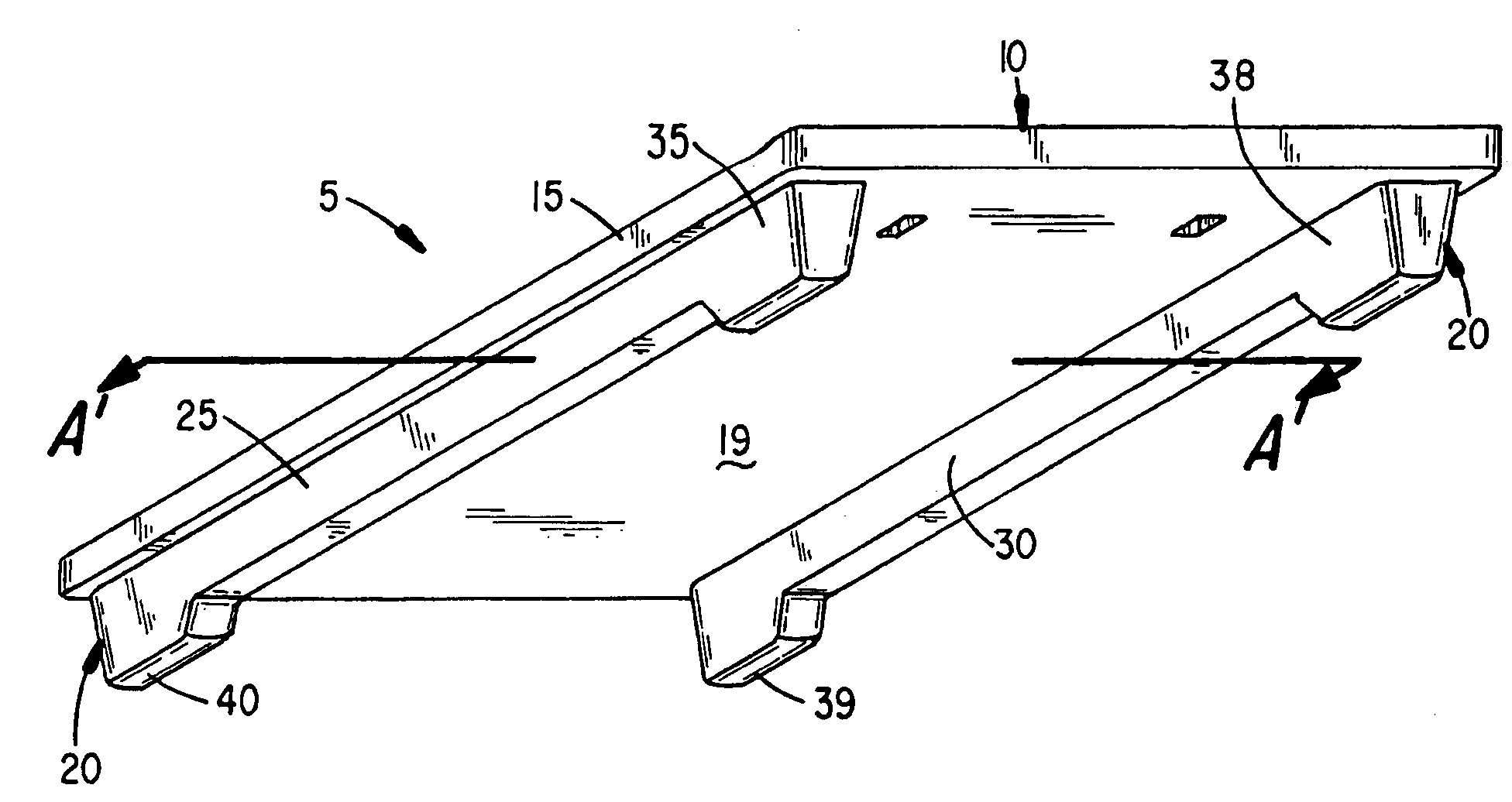
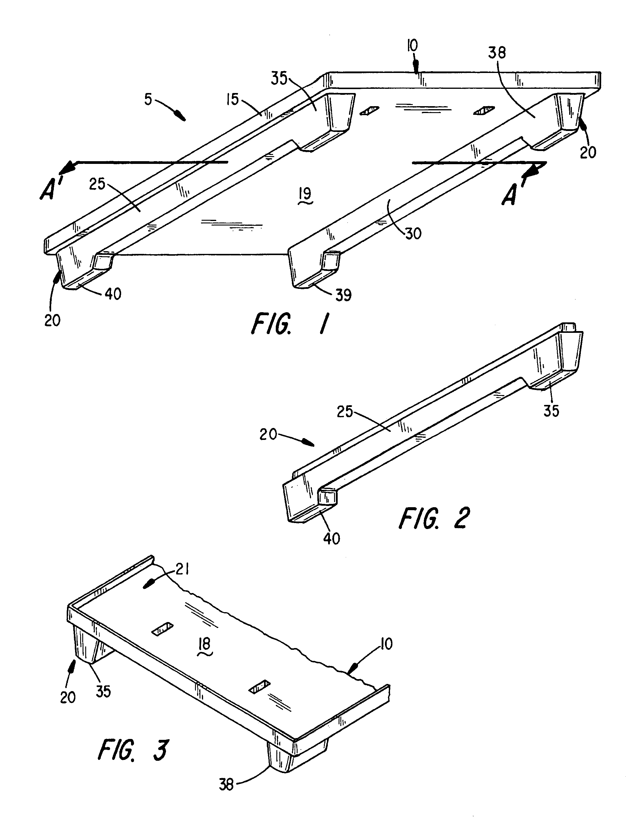
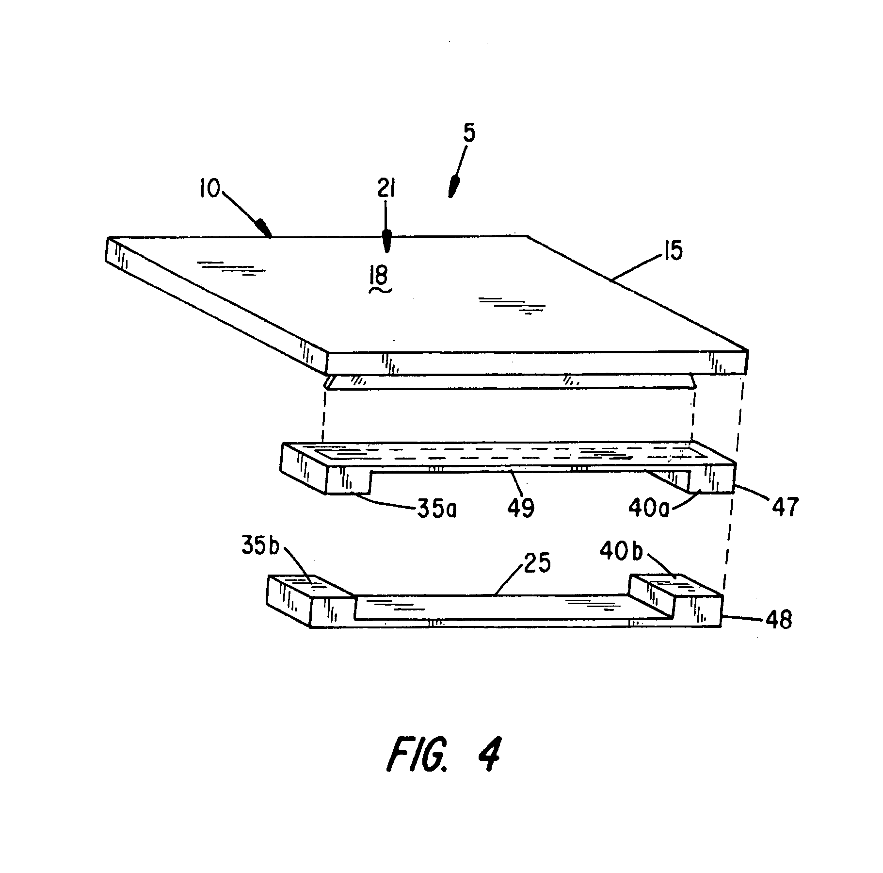
[0057]As shown in FIG. 1, pallet system 5 contains a body 10 which includes an upper or load bearing component or portion 15 and a lower or pallet stabilizing component or portion 20. The upper or second portion 15 preferably includes topside surface 18 and underside surface 19 on a top deck 21. In the lower or first portion 20 may include several feet and / or rails or runners attached thereto. For example, at each of the four corners a first foot 35, a second foot 38, a third foot 39, and a fourth foot 40 may be either integrally or separately formed into the top deck 21. In the preferred embodiment at least two rails, a first rail or runner 25 and a second rail or runner 30, are then either integrally or separately connected to the feet 35, 38, 39 a...


PUM

PropertyMeasurementUnit
weightaaaaaaaaaa
weightaaaaaaaaaa
strength ratioaaaaaaaaaa

Abstract

A pallet system includes a pallet body. The pallet body is formed from a first, independently formed first portion and a second blow molded second upper portion insert molded to the first portion. The pallet body may have two to eight recesses for forklift truck fork access. The second upper portion has a generally rectangular surface for carrying loads. The portions may have anti-skid properties, for example, a knurled topside surface or rubber coated bottom. At least one foot is attached to the second upper portion by insert molding. At least one runner may be attached to each foot to form part of the first portion. At least one stringer is attached to each runner to add further stability to the pallet. The runners and feet have channels or protruding members to effectively mate with the second upper portion. The system may also have top cap and tie members to affix the cap to one or more pallet bodies.

Description

BACKGROUND OF THE INVENTION[0001]1. Field of the Invention[0002]The present invention relates in general to the field of plastics. More particularly, the present invention relates to a pallet system and a pallet apparatus and a method of pallet manufacturing. Specifically, one preferred embodiment of the present invention relates to blow molding a first pallet piece and then inserting it into another mold to join it to a second blow molded pallet piece.[0003]2. Discussion of the Related Art[0004]Pallets are used for transporting and storing various types of cargo throughout the world. Therefore, it is important for a pallet to be lightweight, compact and strong. Traditionally pallets were made of wood, however, plastic pallets are now being used with increased frequency as they are lightweight, generally stronger, do not absorb moisture, and they can be cleaned and disinfected which is important in particular for the food industry. One disadvantage of plastic pallets is that they te...

Claims


Application Information

Patent Timeline
Patent Type & Authority Patents(United States)
IPC IPC(8): B29C49/20B65D19/00
CPCB29C49/20B65D19/0012B65D19/0026B65D19/0028B65D19/0036B29C2049/2017B29C2049/206B29C2791/001B29L2031/7178B65D2519/00034B65D2519/00069B65D2519/00104B65D2519/00129B65D2519/00134B65D2519/00139B65D2519/00208B65D2519/00273B65D2519/00278B65D2519/00288B65D2519/00293B65D2519/00303B65D2519/00318B65D2519/00323B65D2519/00333B65D2519/00338B65D2519/00358B65D2519/00363B65D2519/00373B65D2519/00388B65D2519/00407B65D2519/00412B65D2519/00432B65D2519/00557B65D2519/00567B65D2519/00711B65D2519/00835B65D2519/0084B65D2519/0094B65D2519/00985
Inventor FISCH, ROBERT J.WISER, RANDAL P.SEIBEL, AMY R.MARKLING, FLOYD F.
Owner POLY FLEX INC
Why Eureka
Try Eureka