Fuel distribution device for fuel feed ducts and method of operating distribution device

a technology of fuel distribution device and fuel supply duct, which is applied in the direction of lighting and heating apparatus, combustion types, and combustion using lump and pulverulent fuel, etc. it can solve the problems of low concentration of coal particles in the mixed fluid c that is supplied to burners b>5/b>, unstable fuel ignition characteristics at burners b>5/b>, and distribution of coal particle concentration in the fuel supply du

Inactive Publication Date: 2005-12-20
BABCOCK HITACHI KK
View PDF11 Cites 7 Cited by
  • Summary
  • Abstract
  • Description
  • Claims
  • Application Information

AI Technical Summary

Benefits of technology

[0035]With the above-described fuel supply duct, which is provided at the downstream side with branch ducts that are respectively connected to each of a plurality of burners that open into the furnace, the distribution ratio of the solid fuel carrier gas in the mixed fluid, comprised of a solid-gas two-phase flow, can be made constant and the concentration of the solid fuel can be thickened in an arbitrary direction by adjusting the tilt angle of the damper provided at the upstream side of the above-mentioned part that branches out to the branch ducts. This is enabled since the pressure loss between the damper and the entrances of the respective branch ducts is small in comparison to the total pressure loss from the upstream side of the branching part of the fuel supply duct, through the branch duct burners, and into the furnace, and the distribution ratio of the carrier gas can thus be made constant and inertial separation of just the solid fuel becomes possible. The solid fuel particles can thus be made to undergo a biased flow towards a selected path (each branch duct).
[0061]Also, by operating the above-mentioned damper in the branch duct connected to the lower stage burner in the closing direction when the boiler changes to low load operation after the high load operation condition in which stable combustion of fuel is carried out, the furnace exit gas temperature can be made adequately high for securing the steam temperature required at the demanding end and prevents problems that arise from the lowering of the steam temperature.

Problems solved by technology

Thus, when the load of the boiler is low, the concentration of coal particles in the mixed fluid C that is supplied to burners 5 becomes low and the fuel ignition characteristics at burners 5 can become unstable.
The above described prior art also have the problem that the distribution of the coal particle concentration in the fuel supply duct (main duct) 4, which supplies mixed fluid C from fan mill 3 to the respective stages of burners 5 in boiler furnace 8, is difficult to adjust.
Especially in the case where a boiler is to be operated at low load, if a mixed fluid C of low coal particle concentration is conveyed to a burner 5 to which a mixed fluid C of high coal particle concentration should be conveyed, the combustion condition of the flame can become unstable and cause a flame-out.
When a boiler is to be operated at low load, the mill load must be lowered, and though the supply amount of coal is lowered accordingly, the flow rate of the coal carrier gas cannot be lowered below a predetermined flow rate (minimum flow rate) for stable conveying of the coal particles.
In this case, unless the coal particle concentration is not adjusted appropriately, the combustion of coal becomes unstable and the stable operation of the boiler is made difficult.
However, even if high amounts of concentrated coal particles are supplied to burners of specific stages and the burner ignition stability is improved, the exhaust gas temperature at the furnace exit decreases due to the relationship between heat absorption by the furnace walls in the furnace height direction and the flame temperature distribution within the furnace, thereby preventing the obtaining of the predetermined steam temperature.

Method used


Image

  • Fuel distribution device for fuel feed ducts and method of operating distribution device
  • Fuel distribution device for fuel feed ducts and method of operating distribution device
  • Fuel distribution device for fuel feed ducts and method of operating distribution device

Examples


first embodiment

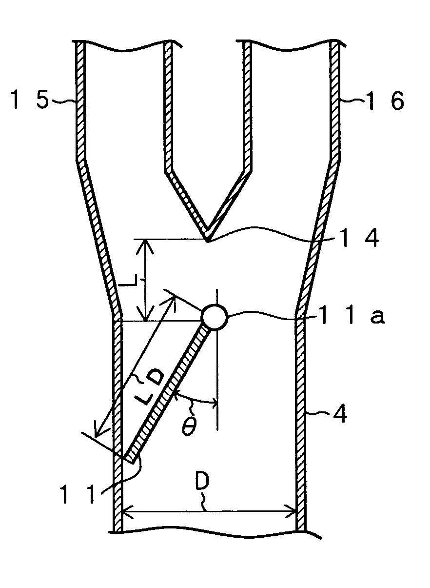
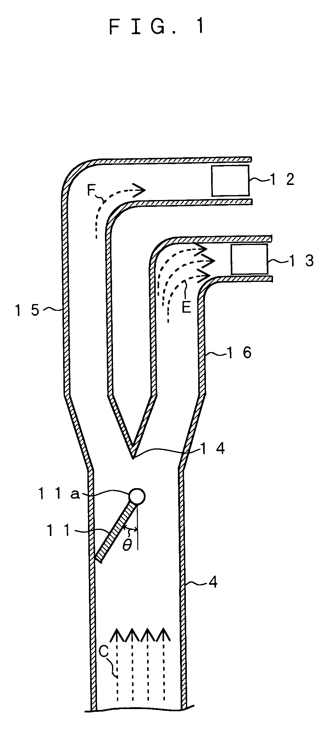
[0092]FIG. 1 is a sectional view of the principal parts of the fuel supply duct of this embodiment and FIG. 2 shows the detailed structure around the damper that is installed in the fuel supply duct of FIG. 1.

[0093]The fuel feeding piping of FIG. 1 is comprised of a main duct 4, which extends in the vertical direction, a damper 11, which is installed at an upstream part inside main duct 4 in the vicinity of a duct branching point 14, and branch ducts 15 and 16 that result from the branching and are connected to an upper stage burner 12 and a lower stage burner 13, respectively.

[0094]With damper 11, a damper pivoting axis 11a is disposed in the direction of crossing the main duct 4 in the vicinity of the central part of main duct 4 as shown in FIG. 2.

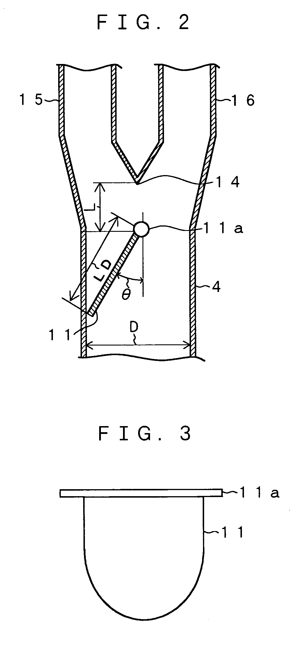
[0095]As shown in FIG. 2, damper pivoting axis 11a is installed at the upper end part of damper 11 with this embodiment. As shown by the plan view of damper 11 in FIG. 3, damper 11 has a substantially semicircular shape and damper pivoti...

second embodiment

[0097]FIG. 4 is a longitudinal sectional view of the principal parts of the fuel supply duct of this embodiment, which is a variation of the first embodiment and FIG. 5, is a plan view of the damper of FIG. 4. Damper 11 has a circular shape that is the same as the cross-sectional shape of main duct 4.

[0098]Damper 11 can be held at an appropriate tilt angle θ upon rotation of damper pivoting axis 11a in this case as well.

[0099]FIG. 6 shows the relationship between the ratio of concentration of coal towards lower stage burner 13 in the first embodiment and second embodiment and the value of (L1 / LD), which is the ratio of the length (L1) from the upper end of damper 11 to pivoting axis 11a with respect to the maximum width (LD) of the damper. The ratio of concentration of coal towards lower stage burner 13 is the ratio of the coal concentration that is supplied to branch duct 16 at the lower stage burner side with respect to the coal concentration in the mixed fluid in main duct 4.

[010...

third embodiment

[0111]FIG. 9 shows an example of a fuel supply duct with a rectangular cross section and having a structure wherein branch ducts 15 and 16, which are connected to and branch out from main duct 4 to upper stage burner 12 and lower stage burner 13, respectively, extend in parallel in the upward direction and are separated from each other in the vicinity of upper and lower stage burners 12 and 13. Damper 11 is provided inside main duct 4 forward where it is branched out to upper stage burner 12 and lower stage burner 13.

[0112]As shown in FIG. 9, damper 11 has an arrangement wherein its pivoting axis 11a is provided at the upstream side of and along a vertical line that passes through branching point 14 and this pivoting axis 11a is provided at the upper end part of damper 11. Since as shown in FIG. 9, damper 11 is tilted towards branch duct 15, which leads towards upper stage burner 12, the concentration of coal particles in the mixed fluid E that is supplied to branch duct 16, which l...


PUM


Abstract

A fuel supply duct, which supplies a mixed fluid of a solid fuel and carrier gas to one or more burners provided on the walls of a furnace, is provided with a branching part, and each of a plurality of branch ducts, which branch out from the branching part, is connected to a corresponding burner. Also a damper, with which the tilt angle with respect to the direction of flow of the mixed fluid can be changed, is positioned in the fuel supply duct at the upstream side of the branching part so that a mutual difference will arise in the solid fuel concentrations of the mixed fluid supplied to the respective branch ducts. A fuel distributor for fuel supply duct is thus arranged. The tilt angle of the above-mentioned damper is adjusted to increase the concentration of solid fuel in the mixed fluid supplied to a specific burner. At a burner to which the high solid fuel concentration is supplied, stability of ignition and stable combustion of the ignited flame can be obtained during low load operation.

Description

BACKGROUND OF THE INVENTION[0001]1. Technical Field[0002]This invention concerns a fuel distributor for a fuel supply duct, a fuel supply system equipped with the aforementioned fuel distributor, and a combustion system equipped with the aforementioned fuel supply system, and in particular, concerns a fuel distributor for a fuel supply duct that is favorable for improving the combustion characteristics of a brown coal fired boiler.[0003]2. Background Art[0004]FIG. 20 shows an example of a prior art brown coal combustion system for a boiler. The brown coal combustion system and the boiler structure are comprised of a coal hopper 1, a mill 3, which pulverizes the coal supplied from said hopper 1, a fuel supply duct 4, which conveys a mixed fluid made up of the coal particles supplied from said mill 3 and a coal particle carrier gas (hereinafter, the coal particles may be referred to as “pulverized coal” and the mixture of coal particles and coal particle carrier gas may be referred to...

Claims


Application Information

Patent Timeline
Patent Type & Authority Patents(United States)
IPC IPC(8): F23C5/28F23C7/00F23K3/02
CPCF23C5/28F23C7/008F23K3/02F23K2201/30F23K2203/105F23K2203/201
Inventor OHTANI, YOSHINORIYOSHIZAKO, HIDEHISAKANEMOTO, HIROAKITAKENO, YUTAKASHIMOGORI, YOSHIOTSUMURA, TOSHIKAZUTAKAHASHI, YOSHITAKA
Owner BABCOCK HITACHI KK
Why Eureka
Try Eureka