Shaft seal structure and turbine
a technology of shaft seals and turbines, applied in the direction of engine seals, gas turbine plants, machines/engines, etc., can solve the problems of weak floating force on each strip b>3/b>, affecting the sealing performance, and reducing the sealing performance, so as to facilitate maintenance and other work on the pushing member, the effect of convenient detachment and easy detachmen
- Summary
- Abstract
- Description
- Claims
- Application Information
AI Technical Summary
Benefits of technology
Problems solved by technology
Method used
Image
Examples
first embodiment
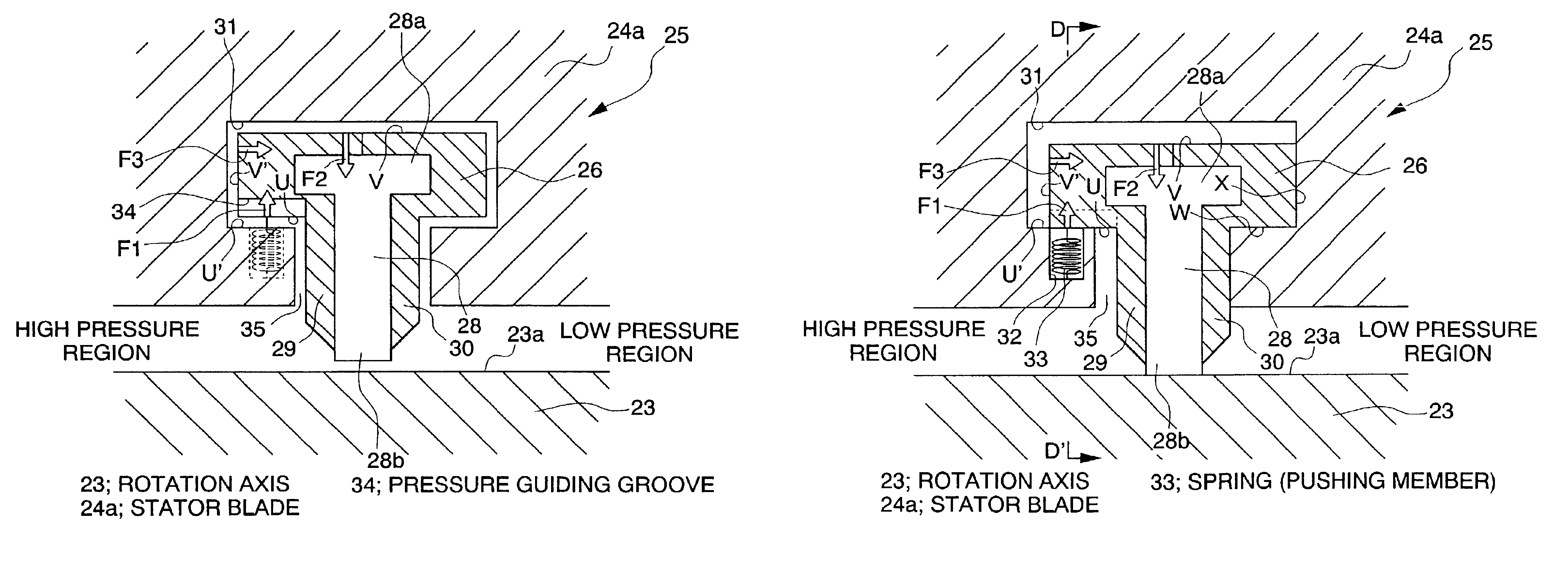
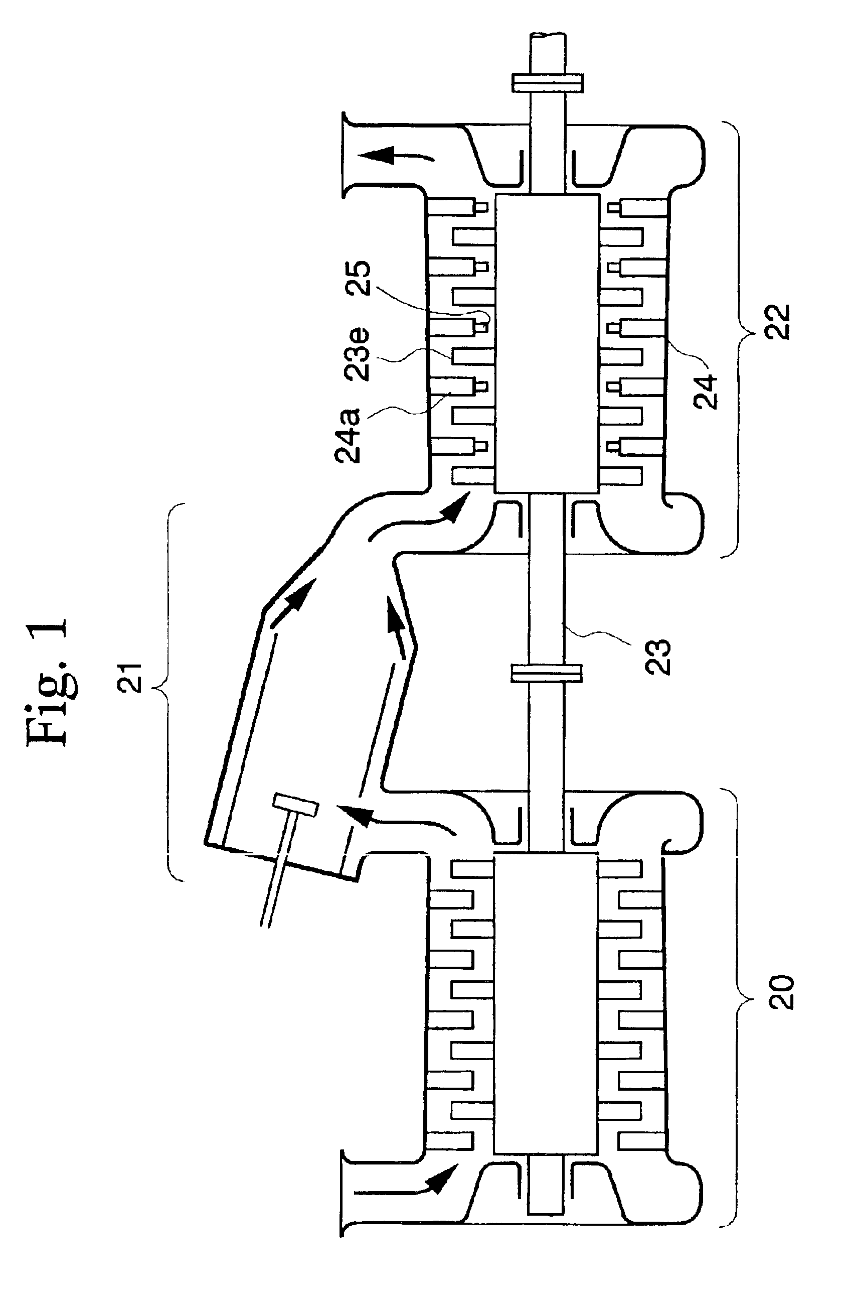
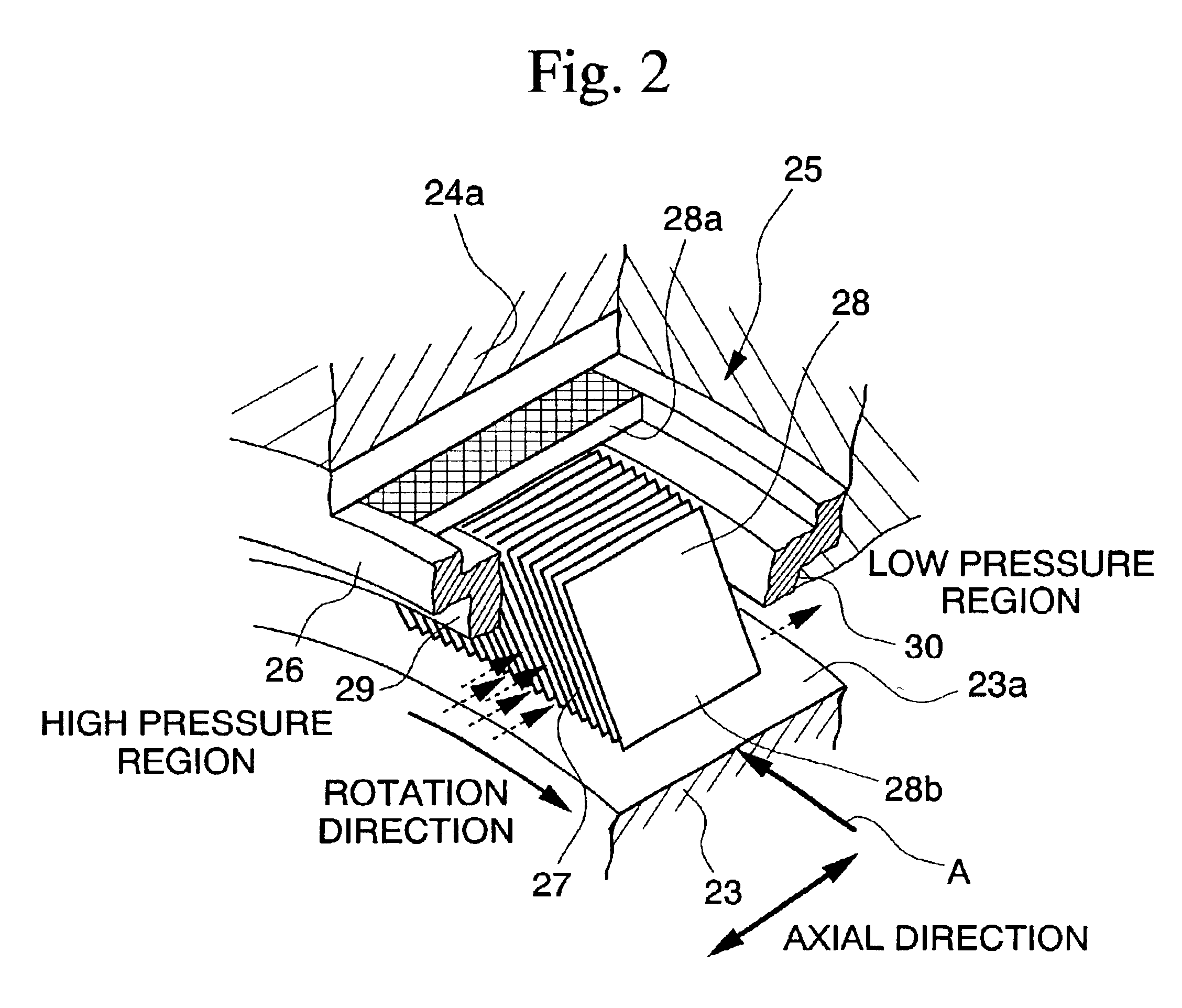
[0054]The first embodiment will be explained with reference to FIGS. 1 to 7.
[0055]FIG. 1 shows a schematic structure of the gas turbine. In the diagram, a reference numeral 20 indicates to a compressor. A reference numeral 21 indicates a burner. A reference numeral 22 indicates a turbine. The compressor 20 introduces a large volume of air therein and compresses the air. Normally, a gas turbine utilizes a portion of the motion power obtained from the rotation shaft 23 as a motion power for the compressor 20. The burner 21 mixes a fuel into the compressed air from the compressor and combusts the gaseous mixture. The turbine 22 admits combustion gas (fluid) generated in the burner 21 and expands the gas so as to blow the expanded gas against the moving blades 23e provided on the rotation shaft 23, thereby converting the thermal energy of the combustion gas into mechanical energy to generate motion power.
[0056]In the turbine 22, in addition to the plurality of moving blades 23e provided...
second embodiment
[0070]the present invention will be explained with reference to FIGS. 8 and 9.
[0071]FIG. 8 shows a cross section of the leaf seal 25 and the stator blade 24a, and FIG. 9 shows a cross section through a plane E-E′ of the leaf seal 25 and the stator blade 24a shown in FIG. 8. A reference numeral 36 in FIGS. 8, 9 indicates a wave-shaped leaf spring. A reference numeral 37 indicates a long hole formed in the concave section 31 of the stator blade 24a for containing the leaf spring 36.
[0072]Accordingly, the leaf seal 25 in the second embodiment utilizes leaf springs 36 instead of the springs 33 used in the leaf seal 25 in the first embodiment.
[0073]According to the leaf seal 25 in the second embodiment, there is no need for fixing each end of the spring 33 to the stator blade 24a and to the leaf seal ring 26, so that by simply inserting the leaf spring 36 in the long hole 37 formed in the stator blade 24a, it is possible to provide the leaf spring 37 between the stator blade 24a and the ...
third embodiment
[0075]Next, the invention will be explained with reference to FIGS. 10 and 11.
[0076]The leaf seal 25 in the third embodiment is designed so that the springs 35 used in the leaf seal 25 in the first embodiment are held individually in holding members that are separated from the stator blade 24a.
[0077]In the following, the holding member will be explained in detail.
[0078]A reference numeral 38 in FIG. 10 indicates a holding member. The holding member 38 comprises a portion obtained by dividing the ring into a plurality of segments in the radial direction, and when attached to the stator blade 24a, forms a concave section 31 for holding the head section of the leaf seal ring 26 in conjunction with the stator blade 24a.
[0079]FIG. 11 is a cross section of the leaf seal 25 and the holding member 34 viewed in a plane F-F′ in FIG. 10. As shown in FIGS. 10 and 11, in the holding member 38, a bolt insertion hole 39 is provided in each end section for inserting a bolt into the stator blade 2...
PUM
 Abstract
Description
Claims
Application Information
 - R&D
- Intellectual Property
- Life Sciences
- Materials
- Tech Scout
- Unparalleled Data Quality
- Higher Quality Content
- 60% Fewer Hallucinations
Browse by: Latest US Patents, China's latest patents, Technical Efficacy Thesaurus, Application Domain, Technology Topic, Popular Technical Reports.
© 2025 PatSnap. All rights reserved.Legal|Privacy policy|Modern Slavery Act Transparency Statement|Sitemap|About US| Contact US: help@patsnap.com


