Transportable medical apparatus

a medical device and transportable technology, applied in the field of transportable medical devices, can solve the problems of not being able to readily adapt to the needs of people, the equipment is relatively heavy and cumbersome to handle, and the equipment is typically not adjustable, so as to facilitate the handling of the undercarriage

Inactive Publication Date: 2005-12-20
NEOMEDTEK
View PDF32 Cites 91 Cited by
  • Summary
  • Abstract
  • Description
  • Claims
  • Application Information

AI Technical Summary

Benefits of technology

[0006]In one aspect, the stowed position of the first pair of legs is located between the upper surface and the lower surface of the support base to thereby provide a compact arrangement. In another aspect, the stowed position of the second pair of legs is between the upper and lower surfaces of the support base. For example, the second pair of legs may be at least partially extended into the support base when moved to their stowed position to thereby provide a compact undercarriage.
[0007]According to yet another aspect, the support base includes a plurality of journaled members that enable a person to translate the undercarriage across the support surface when the first pair of legs are pivoted to their stowed position and also when the second pair of legs are pivoted to their stowed position. The journaled members preferably include at least one pair of forward journaled members to provide support to the support base when the support base is initially loaded onto the support surface and the forward legs are at least initially pivoted. In addition, another group of the journaled members of the support base are preferably located forward of the rearward legs and rearward of the forward legs to form intermediate journaled members such that the intermediate journaled members provide support for the undercarriage when the forward legs are fully pivoted to their stowed position to thereby ease handling of the undercarriage. For example, the intermediate journaled members may be located at or near the center of gravity of the undercarriage and are optionally located rearward of the center of gravity.

Problems solved by technology

The equipment, however, is relatively heavy and cumbersome to handle.
Furthermore, the equipment is typically not adjustable and, therefore, cannot readily adapt to the needs of the persons, most often paramedics, who handle the equipment.

Method used


Image

  • Transportable medical apparatus
  • Transportable medical apparatus
  • Transportable medical apparatus

Examples


Embodiment Construction

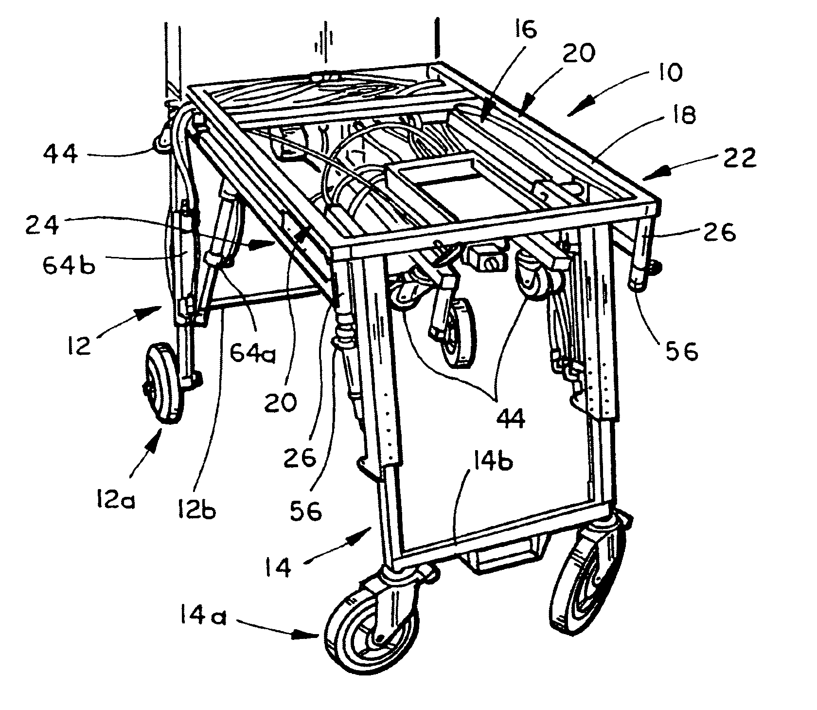
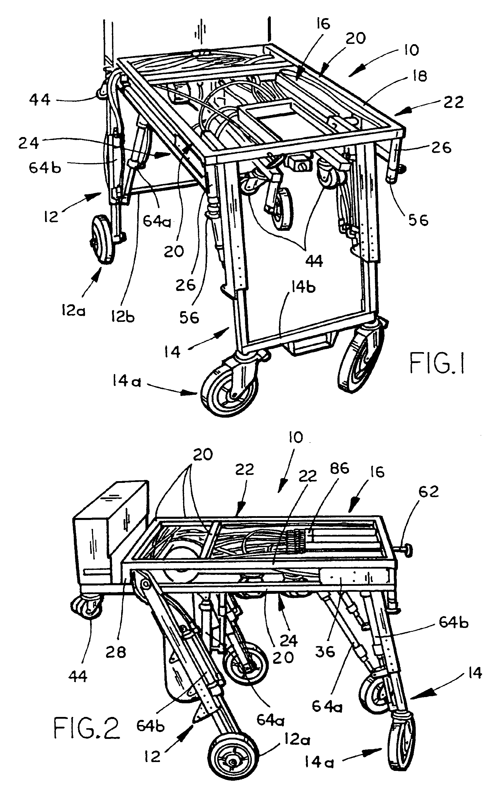
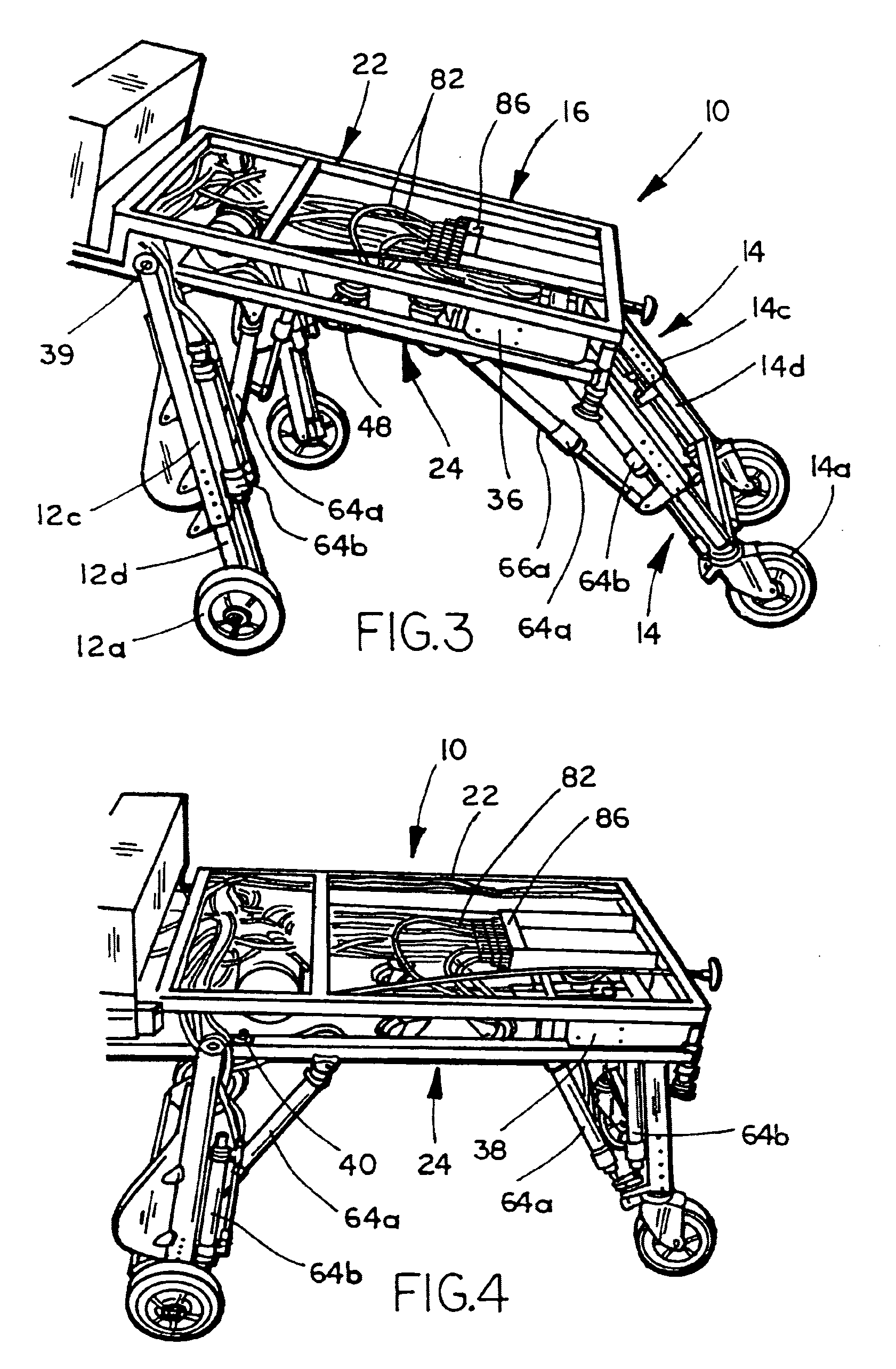
[0045]Referring to FIG. 1, the numeral 10 generally designates an undercarriage of the present invention. Undercarriage 10 is particularly suitable for use in transporting a stretcher (not shown) and for loading the stretcher onto a vehicle, including an aircraft, such as a helicopter. As will be more fully described below, undercarriage 10 includes a support base 18, a forward pair of legs 12, and a rearward pair of legs 14, which are pivotally mounted to support base 18 and are selectively pivoted to stowed positions so that undercarriage 10 can be loaded onto the vehicle (not shown). In addition, undercarriage 10 includes a control system 16 that enables the person loading the undercarriage to control the pivoting of the respective legs and, further, to raise and lower the height of the support base 18 to ease handling of undercarriage 10. As will be appreciated from the following description, support base 18 is configured and legs 12 and 14 are pivoted in a manner to permit a si...


PUM


Abstract

An undercarriage for transporting a stretcher includes a support base, which is adapted for supporting a stretcher, a first pair of legs pivotally mounted to the support base, and a second pair of legs pivotally and slidably mounted to the support base. The first pair of legs is independently pivotal about the support base from the second pair of legs. In addition, a journaled member is provided at the distal ends of each leg. The undercarriage also includes a control system that is adapted to selectively pivot the first pair of legs to a stowed position and to selectively pivot the second pair of legs to a stowed position. The control system is further adapted to selectively lengthen or shorten the legs to adjust the height of the support base.

Description

[0001]This application claims priority from provisional application entitled TRANSPORTABLE MEDICAL APPARATUS, Ser. No. 60 / 407,348, filed Aug. 30, 2002, which is incorporated herein by reference in its entirety.TECHNICAL FIELD AND BACKGROUND OF THE INVENTION[0002]The present invention is generally directed to a transportation device for transporting a person, especially in a medical situation.[0003]Transportation equipment for patients, such as cots or stretchers, which are used to transport a patient in a vehicle, such as an ambulance or aircraft, including a helicopter, are well known. Most equipment of this type include a wheeled undercarriage and a stretcher that is removably mounted to the undercarriage. The equipment, however, is relatively heavy and cumbersome to handle. As a result, the equipment usually requires two or more persons to load the equipment onto the vehicle. Furthermore, the equipment is typically not adjustable and, therefore, cannot readily adapt to the needs ...

Claims


Application Information

Patent Timeline
Patent Type & Authority Patents(United States)
IPC IPC(8): A61G1/02A61G1/056A61G1/06
CPCA61G1/0562A61G1/0237A61G1/0262A61G1/0212A61G1/0293
Inventor O'KRANGLEY, JASON M.KRUITHOFF, DAVID M.
Owner NEOMEDTEK
Why Eureka
Try Eureka