Small drill

a small drill and drill bit technology, applied in the field of cutting tools, can solve the problems of reduced accuracy of hole position, low hole-forming speed, and possible cutting portion breakage, and achieve the effect of improving the ability of small drill bit and sufficient position accuracy

Inactive Publication Date: 2005-12-20
MITSUBISHI MATERIALS CORP
View PDF9 Cites 6 Cited by
  • Summary
  • Abstract
  • Description
  • Claims
  • Application Information

AI Technical Summary

Benefits of technology

[0012]In consideration of the above-described situation, an object of the present invention is to provide a small drill for forming deep, small-diameter holes which has sufficient rigidity and chip dischargeability, and which is able to form holes with high positional accuracy.
[0014]Since only one chip-discharging flute is formed in the cutting portion of the small drill, the core diameter is larger compared to the conventional small drill, in which two chip-discharging flutes are formed. Accordingly, the rigidity of the small drill is ensured, and holes may be formed with stable positional accuracy. In addition, the flute-shaped portion, which is formed in the front region of the chip-discharging flute in the rotating direction, has sufficient space for discharging chips. Thus, the produced chips may be discharged not only through the chip-discharging flute but also through the flute-shaped portion. Accordingly, chip dischargeability is improved, and clumping of the chips and the breakage of the small drill may be prevented.
[0019]During the cutting process, the margin contacts the inner wall of the hole which is being formed, and serves to remove the produced burrs. In addition, the margin also serves to counterbalance a force applied to a cutting edge in the radial direction, and to improve the ability of the small drill to advance straightly by guiding the cutting portion thereof. When the margin angle is smaller than 120°, the ability of the small drill to advance straightly will be degraded, so that sufficient positional accuracy may not be obtained.

Problems solved by technology

Thus, the accuracy of the hole position is reduced, and breakage of the cutting portion may occur.
Although such problems may be solved by employing step feeding, the hole-forming speed will be extremely low, and productivity will be greatly degraded.
Accordingly, chip dischargeability is degraded, so that the chips may clump together inside the flute and failure to discharge the chips may occur.
Accordingly, the space inside the body clearance 5 is not sufficient for discharging the chips, so the body clearance 5 does not serve to discharge the chips.
As a result, when a hole having an extremely small diameter, such as 0.5 mm or less, and an extremely large ratio of diameter to depth, such as 10 or more, is formed, failure to discharge the chips may frequently occur.

Method used


Image

  • Small drill
  • Small drill
  • Small drill

Examples


first embodiment

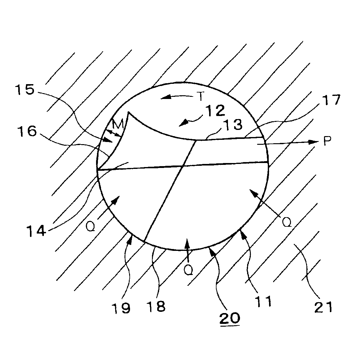
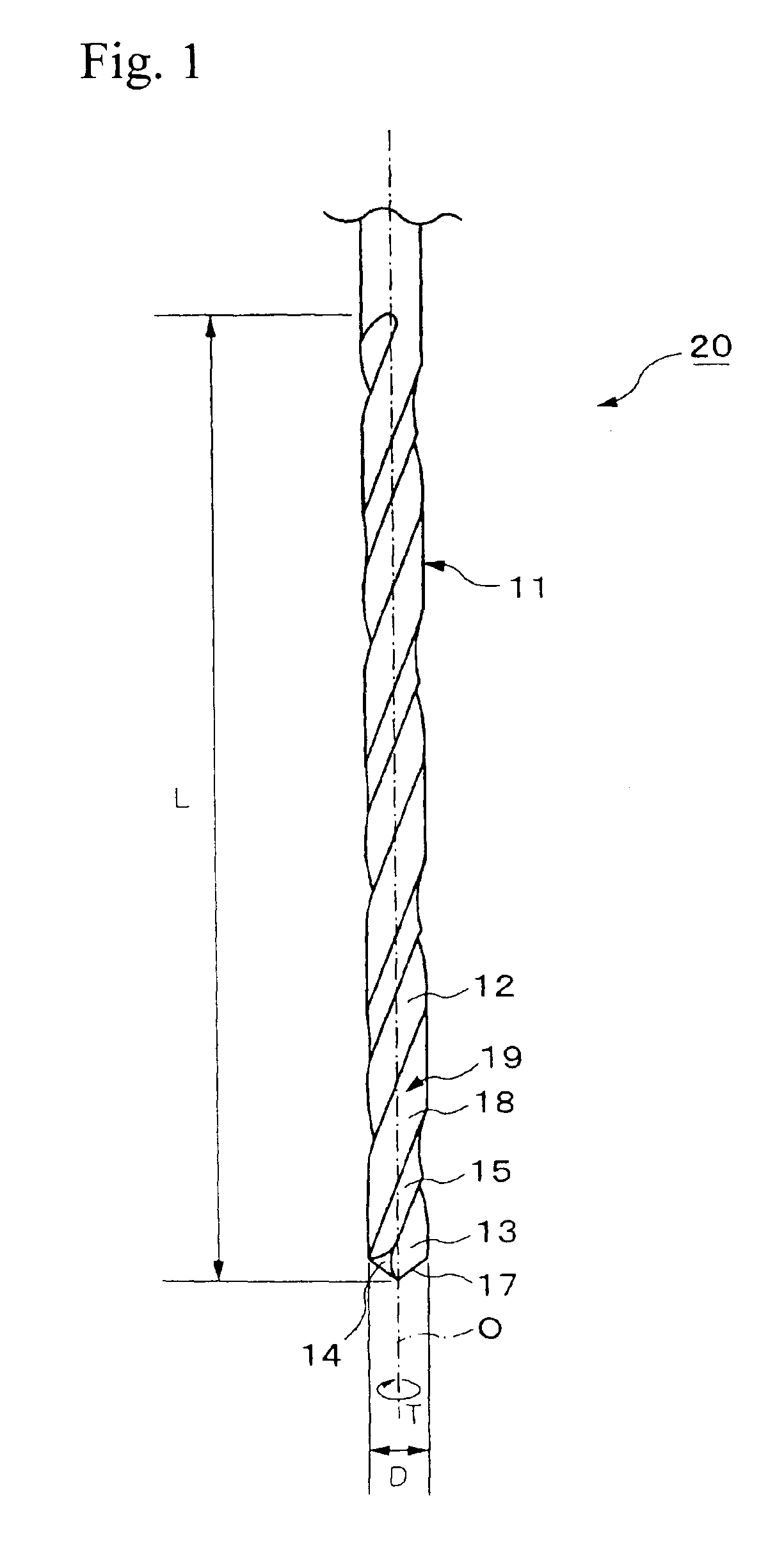
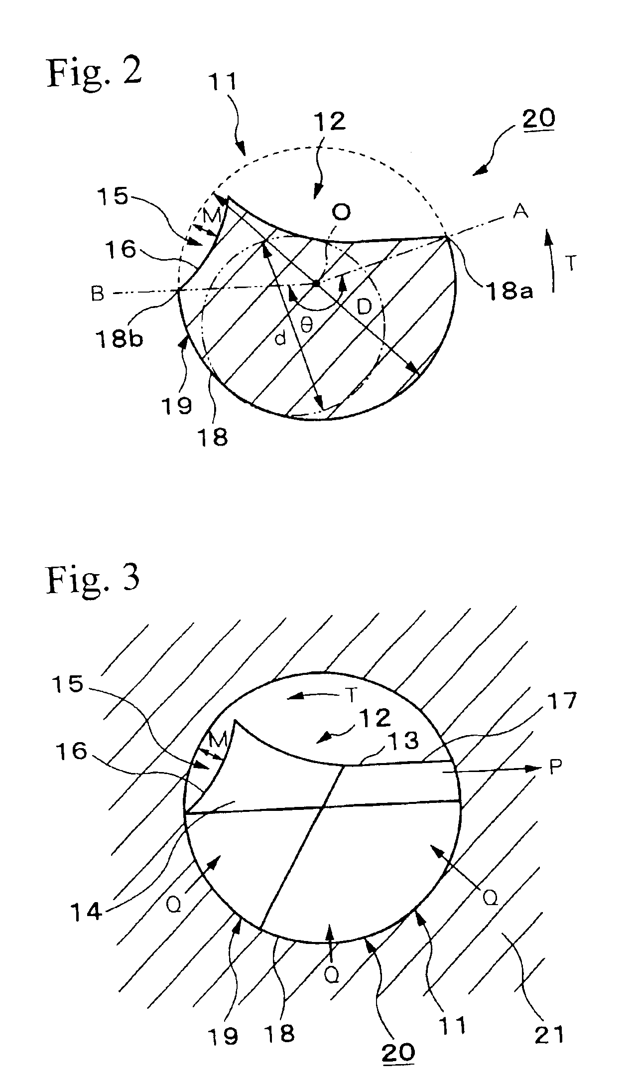
[0031]FIG. 1 is a side view of a small drill according to the present invention, and FIG. 2 is a sectional view of a cutting portion of the small drill shown in FIG. 1.

[0032]The small drill 20 according to the first embodiment of the present invention includes a cutting portion 11 and a shank portion. As shown in FIG. 1, the cutting portion 11 has an approximately columnar shape, and has a small diameter about 0.05 to 1 mm. In addition, the cutting portion 11 is of a straight type, in which the outer diameter D does not change from the tip end to the other end. Thus, the outer diameter D of the cutting portion 11 is the same as the maximum outer diameter D.

[0033]A chip-discharging flute 12 is helically formed in the exterior surface of the cutting portion 11 around the rotational axis O from the tip end toward the other end.

[0034]In addition, a flute-shaped portion 15 is also helically formed in the exterior surface of the cutting portion 11 around the rotational axis O from the tip...

fourth embodiment

[0059]As shown in FIG. 6, in the small drill 50 the land 19, which is the external surface excluding the chip-discharging flute 12 and the flute-shaped portion 15, includes the margin 18 and a body clearance 19a. Similar to the chip-discharging flute 12, the body clearance 19a is helically formed in the direction opposite to the rotating direction T from the tip end toward the other end. The margin 18 is formed in the region directly behind the chip-discharging flute 12 in the rotating direction T, and the body clearance 19a is formed in a region directly behind the margin 18. In addition, the depth “b” of the body clearance 19a is constant.

[0060]The margin angle θ is set to, for example, 150°, and the core diameter ratio d / D, in percent, is set to, for example, 65%.

[0061]Due to the body clearance 19a, which is formed with the constant depth “b” for reducing the friction between the land 19 and the inner wall of the hole as described above, the contact area between the margin 18 an...

fifth embodiment

[0064]As shown in FIG. 7, in the small drill 60 the land 19, which is the external surface excluding the chip-discharging flute 12 and the flute-shaped portion 15, includes a first margin 23, a second margin 24, and the body clearance 19a. Similar to the chip-discharging flute 12, the body clearance 19a is helically formed in the direction opposite to the rotating direction T from the tip end toward the other end. The first margin 23 is formed in a region directly behind the chip-discharging flute 12, and the body clearance 19a is formed in a region directly behind the first margin 23. In addition, the second margin 24 is formed in a region directly behind the body clearance 19a.

[0065]The effects obtained by the first to the fourth embodiment may also be obtained by the small drill 60 of the fifth embodiment. In the case of forming a hole in a work material, both the first and the second margins 23 and 24 contact the inner wall of the hole which is being formed, and receive forces...


PUM

PropertyMeasurementUnit
diameteraaaaaaaaaa
angleaaaaaaaaaa
diameteraaaaaaaaaa

Abstract

A small drill includes one chip-discharging flute which is helically formed in the exterior surface of a cutting portion of the small drill. The small drill also includes a flute-shaped portion which is formed in the front region of the chip-discharging flute in the rotating direction, which is connected to the chip-discharging flute, and which is open at the exterior surface of the cutting portion. The core diameter ratio d / D, in percent, of the small drill is set to 60% or more, and a margin angle θ thereof is set to 120° or more.

Description

[0001]This application is a U.S. national phase application under 35 U.S.C. §371 of International patent application No. PCT / JP01 / 02708 filed Mar. 30, 2001, and claims the benefit of Japanese patent application No. 2000-346953 filed Nov. 14, 2000 both of which are incorporated by reference herein.BACKGROUND OF THE INVENTION[0002]1. Field of the Invention[0003]The present invention relates to a cutting tool, such as a small drill, which is primarily used for forming deep, small-diameter holes in printed circuit boards.[0004]The present application is based on Japanese patent application No. 2000-346953, the contents of which are incorporated by reference into this specification.[0005]2. Background Art[0006]Generally, small drills are expected to form holes having extremely small diameters. Typical small drills have a rod-shaped cutting portion having a small diameter of about 0.05 to 3.175 mm and a shank portion having a relatively large diameter which is connected to a rotating shaf...

Claims


Application Information

Patent Timeline
Patent Type & Authority Patents(United States)
IPC IPC(8): B23B51/02B23B51/00
CPCB23B51/02B23B2251/201B23B2251/241Y10T408/9097Y10S408/705Y10T408/89B23B2251/406B23B51/00
Inventor KANEKO, KAZUHIROODANI, NIRO
Owner MITSUBISHI MATERIALS CORP
Why Eureka
Try Eureka