
Small drill

Inactive Publication Date: 2004-02-26
MITSUBISHI MATERIALS CORP
View PDF3 Cites 7 Cited by
  • Summary
  • Abstract
  • Description
  • Claims
  • Application Information

AI Technical Summary

Benefits of technology

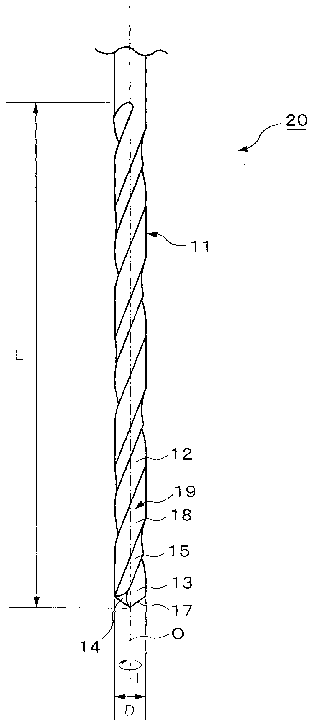
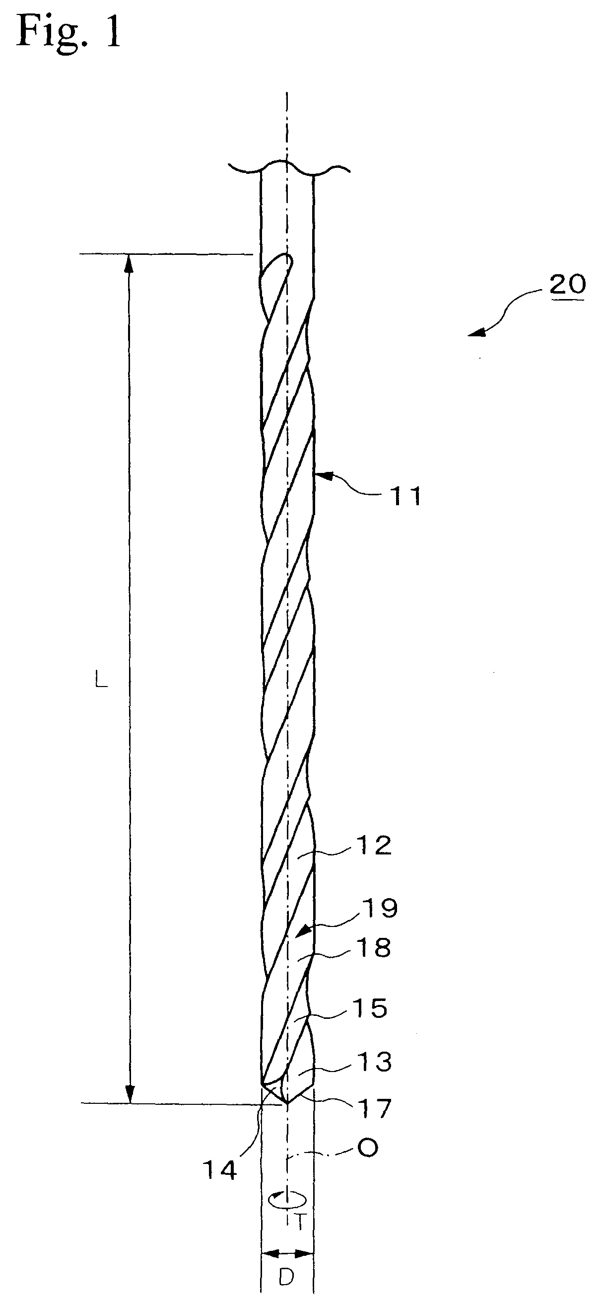
[0011] In consideration of the above-described situation, an object of the present invention is to provide a small drill for forming deep, small-diameter holes which has sufficient rigidity and chip dischargeability, and which is able to form holes with high positional accuracy.

Problems solved by technology

Thus, the accuracy of the hole position is reduced, and breakage of the cutting portion may occur.
Although such problems may be solved by employing step feeding, the hole-forming speed will be extremely low, and productivity will be greatly degraded.
Accordingly, chip dischargeability is degraded, so that the chips may clump together inside the flute and failure to discharge the chips may occur.
Accordingly, the space inside the body clearance 5 is not sufficient for discharging the chips, so the body clearance 5 does not serve to discharge the chips.
As a result, when a hole having an extremely small diameter, such as 0.5 mm or less, and an extremely large ratio of diameter to depth, such as 10 or more, is formed, failure to discharge the chips may frequently occur.
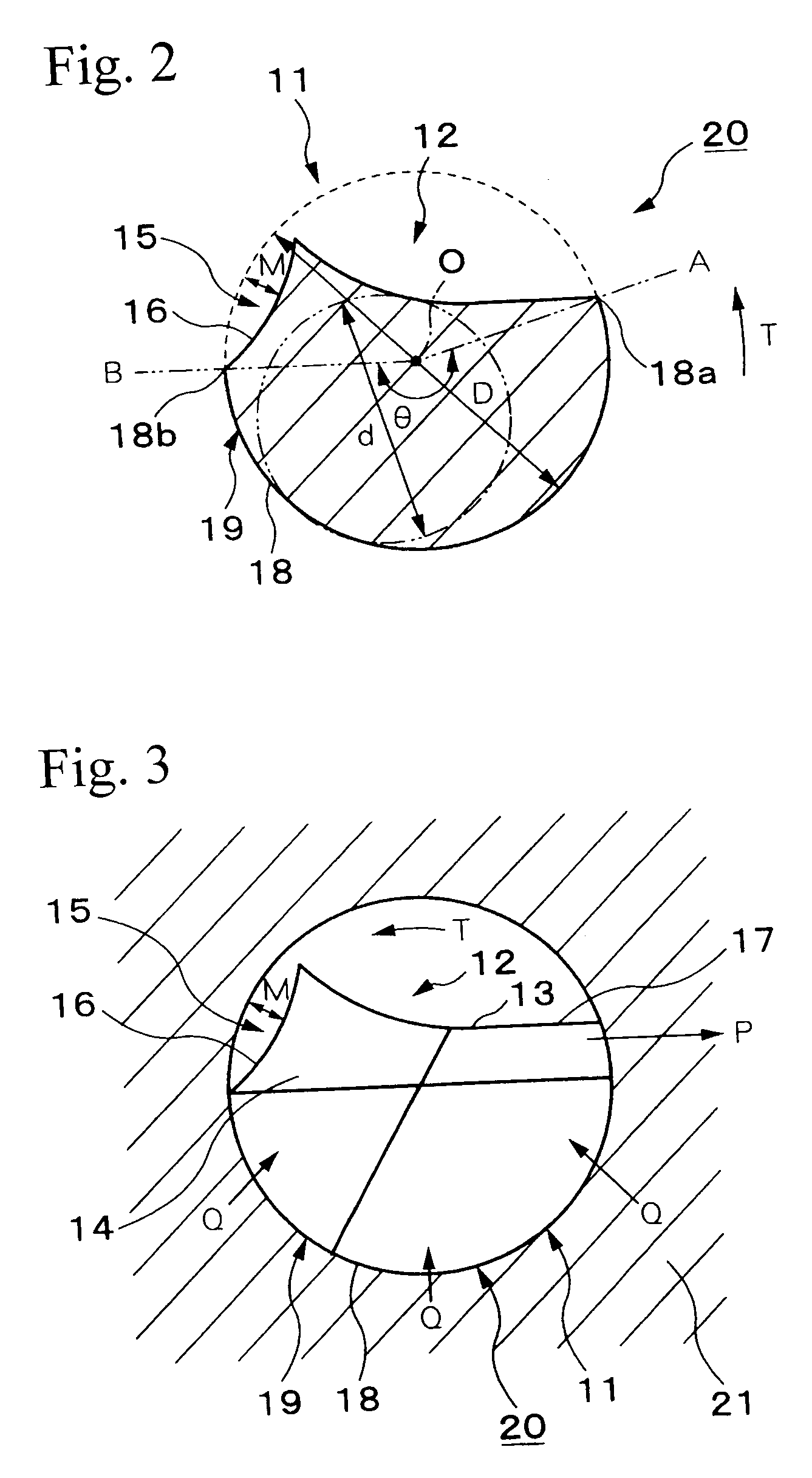
In contrast, when the core diameter ratio d / D, in percent, is less than 60%, the core diameter will be reduced, and sufficient rigidity may not be obtained.
When the margin angle is smaller than 120.degree., the ability of the small drill to advance straightly will be degraded, so that sufficient positional accuracy may not be obtained.
When the margin angle .theta. is smaller than 120.degree., the ability to guide the small drill is degraded, and the rotation of the small drill around the rotational axis O is unbalanced.
Thus, the ability of the small drill to advance straightly is degraded, and the positional accuracy of the formed hole is reduced.
Thus, chip dischargeability is also degraded.

Method used


Image

  • Small drill
  • Small drill
  • Small drill

Examples


Embodiment Construction

60 120 6200 Example 2 60 150 6500 Example 3 65 150 6700 Example 4 65 180 6800 Example 5 70 240 7100 Conventional -- -- 1400 example 1 Conventional 60 60 3800 example 2 Conventional 70 120 2800 example 3 Conventional 80 180 1800 example 4

[0073] Each of the small drills of the examples of the present invention, the comparative examples, and the conventional examples was of the straight type, in which the outer diameter was 0.1 mm from the tip end to the other end of the cutting portion 11. In addition, the effective cutting length L of the cutting portion 11 of each of the examples of the present invention, the comparative examples, and the conventional examples was 1.2 mm. A stack of four double-sided BT resin plates, each of which was 0.2 mm in thickness, was prepared as a work material, and a covering plate (0.2 mm thick LE400) and a bottom plate (1.6 mm thick bakelite resin) were applied thereon during the hole forming process. Holes were formed in units of one hundred under the f...


PUM

PropertyMeasurementUnit
Fractionaaaaaaaaaa
Angleaaaaaaaaaa
Lengthaaaaaaaaaa

Abstract

A small drill includes one chip-discharging flute which is helically formed in the exterior surface of a cutting portion of the small drill. The small drill also includes a flute-shaped portion which is formed in the front region of the chip-discharging flute in the rotating direction, which is connected to the chip-discharging flute, and which is open at the exterior surface of the cutting portion. The core diameter ratio d / D, in percent, of the small drill is set to 60% or more, and a margin angle theta thereof is set to 120° or more.

Description

[0001] 1. Field of the Invention[0002] The present invention relates to a cutting tool, such as a small drill, which is primarily used for forming deep, small-diameter holes in printed circuit boards.[0003] The present application is based on Japanese patent application No. 2000-346953, the contents of which are incorporated by reference into this specification.[0004] 2. Background Art[0005] Generally, small drills are expected to form holes having extremely small diameters. Typical small drills have a rod-shaped cutting portion having a small diameter of about 0.05 to 3.175 mm and a shank portion having a relatively large diameter which is connected to a rotating shaft of a machine tool. The cutting portion and the shank portion are integrally formed, or are connected to each other by soldering, by interference fit, etc. The cutting portion is usually constructed of a cemented carbide, and the shank portion is usually constructed of a cemented carbide, steel, etc.[0006] In conventi...

Claims


Application Information

Patent Timeline
IPC IPC(8): B23B51/02B23B51/00
CPCB23B51/02B23B2251/201B23B2251/241Y10T408/9097Y10S408/705Y10T408/89B23B2251/406B23B51/00
Inventor KANEKO, KAZUHIROODANI, NIRO
Owner MITSUBISHI MATERIALS CORP
Learn More