Positive locking fastener

a technology of positive locking and fasteners, which is applied in the direction of threaded fasteners, screws, fastening means, etc., can solve the problems of not providing the method of increasing the rotational friction does not provide a positive stopping force against the rotation of the nu

Inactive Publication Date: 2005-12-20
GRAINGER PHILLIP T
View PDF14 Cites 91 Cited by
  • Summary
  • Abstract
  • Description
  • Claims
  • Application Information

AI Technical Summary

Benefits of technology

[0017]The present invention further provides a positive locking fastener for inhibiting rotation of a nut located on a shaft of a threaded fastener, the positive locking fastener including a first plate and a second plate receivable on the shaft, wherein at least one of the plates is rotationally fixed relative to the shaft, a locking assembly axially coupling the first plate to the second plate, the locking assembly including an opening formed in th...

Problems solved by technology

Often fasteners may loosen as a result of vibration or thermal expansion.
Although these types of lock washers inhibit rotation of the nut by increasing the frictional forces acting opposite to the nut's rotation, they do not provide a positive rotation stopping force.
As in the case of lock washers, these...

Method used


Image

  • Positive locking fastener
  • Positive locking fastener
  • Positive locking fastener

Examples


first embodiment

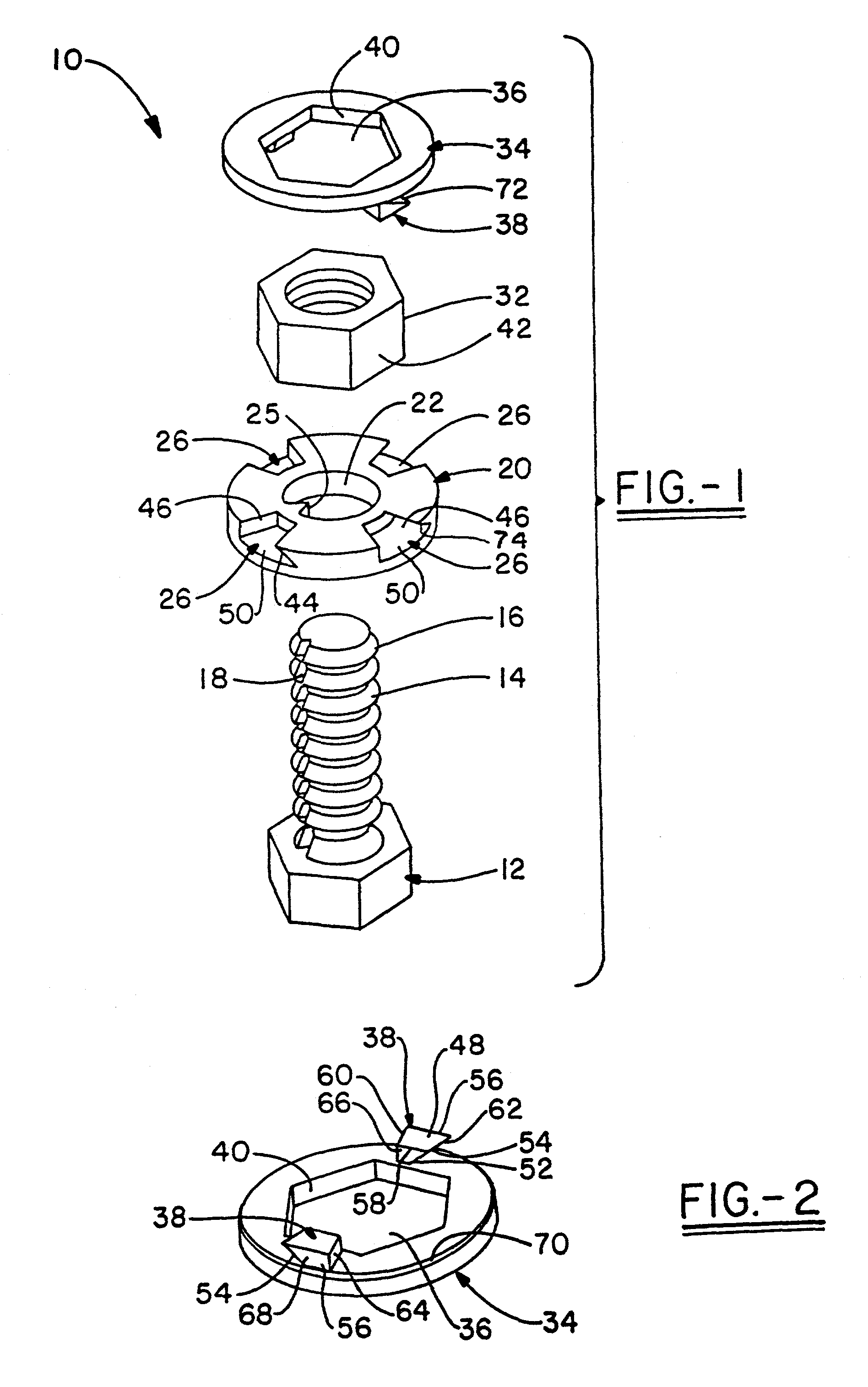
[0030]a positive locking fastener according to the present invention is shown in FIG. 1. The positive locking fastener of the present invention is referred to generally by the numeral 10 in the accompanying figures. Positive locking fastener 10 may be constructed of any material common in the fastening art including woods, metals, plastics, and ceramic materials. The choice of material, as can be appreciated, is largely determined by the end use of the fastener. The positive locking fastener 10 includes a threaded fastener 12 having a shaft 14 carrying a plurality of threads 16. The threaded fastener 12 may be provided with an axial groove 18 that may be used to prevent rotation of washer 20, as will be described below.

[0031]Washer 20 has a hole 22 adapted to slide over the shaft 14 of threaded fastener 12. As shown, washer 20 carries a key 25 adapted to be received within axial groove 18. To slip washer 20 over threaded fastener 12, the key 25 and axial groove 18 are aligned, and t...

fourth embodiment

[0048]In the invention, shown in FIG. 5, the positive locking fastener 310 includes a threaded fastener (not shown), a washer 320 and a nut 332. Washer 320 and threaded fastener are rotationally locked together as described above. Nut 332 is rotationally coupled to washer 320 by a locking assembly 330. Locking assembly 330 includes a flange 390 extending radially outwardly from the nut 332. The flange 390 carries a shaped projection 391 that corresponds to a similar projection 392 on the circumference of the washer 320. The locking assembly 330 further includes a locking ring 394 for receiving the shaped projections on the washer 320 and nut 332. Locking ring 394 couples washer 320 to nut 332, such that one cannot rotate without the other. As shown in FIG. 5, locking ring 394 has a first side 395 and a second side 396 joined by a hinge 397. When the projections 391, 392 are aligned, lock ring 394 encircles the projections 391, 392 on washer 320 and nut 332 receiving these projection...


PUM


Abstract

A positive locking fastener for inhibiting rotation of a nut located on a shaft of a threaded fastener, the positive locking fastener comprising: a first plate and a second plate receivable on the shaft, wherein at least one of said plates is rotationally fixed relative to the shaft; a locking assembly axially coupling said first plate to said second plate, said locking assembly including an opening formed in said second plate and a projection extending axially outward from said first plate, wherein said projection is adapted to extend through said opening and overlap a portion of said second plate; and a nut receiving aperture formed on one of said plates having a nut engaging member adapted to rotationally couple the nut to said plates, whereby the nut is rotationally fixed relative to the shaft to inhibit rotation of the nut.

Description

RELATED APPLICATIONS[0001]This application is a continuation-in-part of U.S. patent application Ser. No. 09 / 475,341 filed Dec. 30, 1999 now abandoned.TECHNICAL FIELD[0002]The present invention generally relates to fasteners. More particularly, the present invention relates to a vibration resistant fastener. Even more particularly, the present invention relates to a positive locking fastener that resists loosening caused by vibration by locking the fastener such that it cannot rotate.BACKGROUND OF THE INVENTION[0003]Fasteners are well known in the art. Often fasteners may loosen as a result of vibration or thermal expansion. To alleviate this problem, a wide variety of lock washers have been developed in the art. Lock washers attempt to prevent loosening by increasing the frictional forces between the nut and a stationary surface. Some examples include, a split ring lock washer, a star lock washer, or spring washers. Although these types of lock washers inhibit rotation of the nut by...

Claims


Application Information

Patent Timeline
IPC IPC(8): F16B39/10
CPCF16B39/103
Inventor GRAINGER, PHILLIP T.
Owner GRAINGER PHILLIP T
Why Eureka
Try Eureka