Prosthetic device and method of making the same

a technology of prosthetic devices and components, applied in the field of prosthetic orthopedic implants, can solve the problems of non-moldable materials, difficult and time-consuming cross-linking of bearing components, and the method of producing monoblock devices,

Inactive Publication Date: 2005-12-20
ZIMMER TECH INC
View PDF16 Cites 66 Cited by
  • Summary
  • Abstract
  • Description
  • Claims
  • Application Information

AI Technical Summary

Benefits of technology

[0012]An advantage of the present invention is that a cross-linked polymer component may be attached to a metal component rather than attaching a non-cross-linked polymer and subsequently irradiating the same to create cross-links as the metal component may make such subsequent irradiation difficult.
[0013]Another advantage of the present invention is that the bearing surface may comprise a variety of materials, such as, thermoplastics, thermosets, metals, and ceramics, yet still be bonded the porous metal component.
[0014]These and other advantages and features of the present invention will be apparent to those skilled in the art upon review of the appended claims and drawings.

Problems solved by technology

However, this method of producing monoblock devices has disadvantages.
A problem with this process is that the metal component of the monoblock device can shield the bearing component from the electron beam radiation used to initiate cross linking, thereby making cross linking of the bearing component more difficult and time consuming or possibly having areas within the polymer remaining uncrosslinked.
Another problem with monoblock processes known in the art is that such processes do not accommodate using non moldable materials such as metals or ceramics for the bearing surface, as the same cannot be compression or injection molded onto a backing component.

Method used


Image

  • Prosthetic device and method of making the same
  • Prosthetic device and method of making the same
  • Prosthetic device and method of making the same

Examples


Embodiment Construction

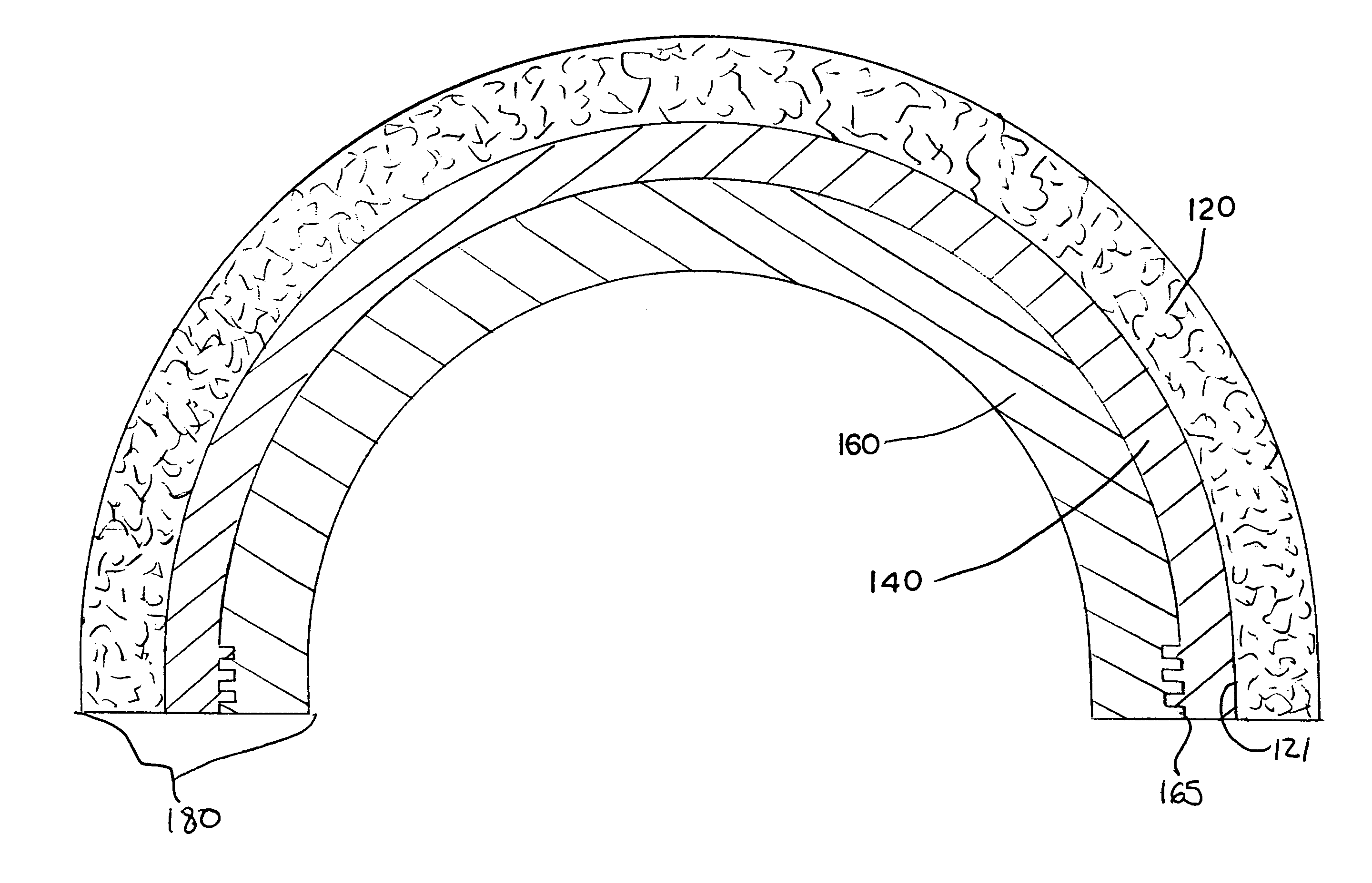
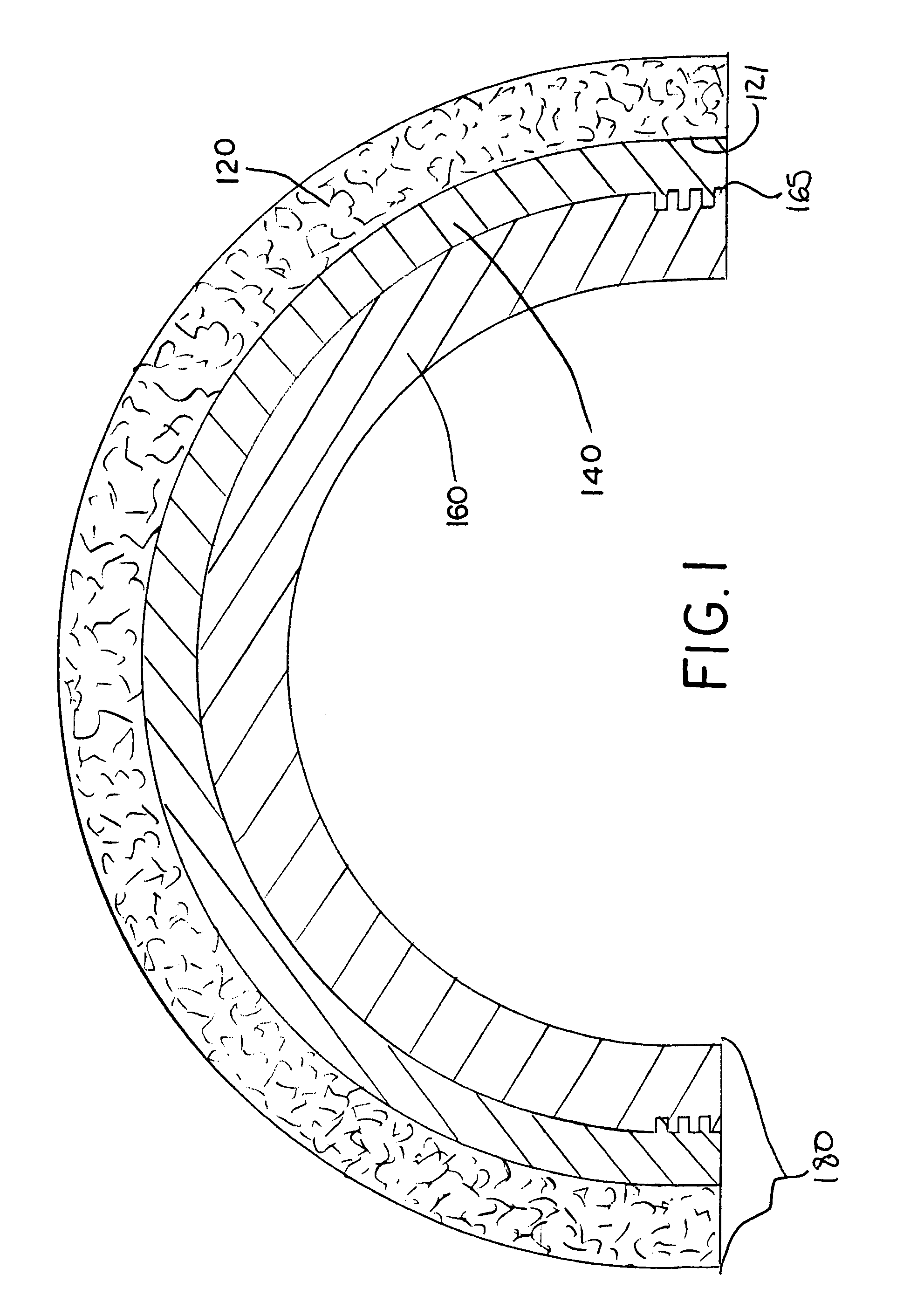
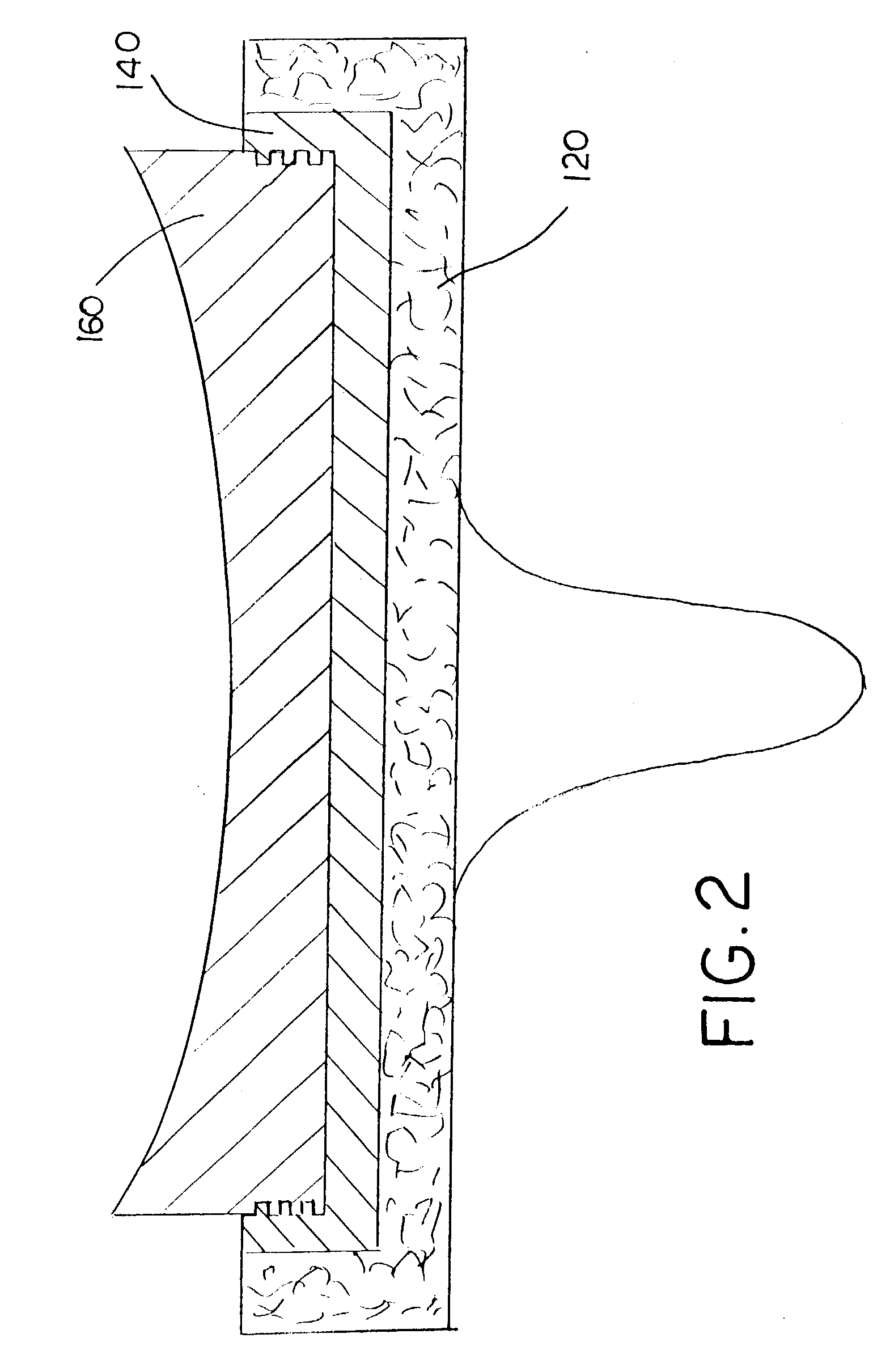
[0023]The present invention comprises a method of making a monoblock prosthetic device, having a porous metal component. FIGS. 1 and 2 show exemplary devices that can be made using the present method, including an acetabular cup for a hip prosthesis and a tibial plateau for a knee prosthesis. It will be appreciated by those of skill in the art that other prosthetic devices comprising a metal component and bearing component, such as, glenoid components for shoulder prostheses and the like could also be made by the present method.

[0024]Referring now to FIG. 3, there is shown a diagrammatical view of a first embodiment 300 of the present method. The method comprises the steps of: providing metal backing component 120 of desired shape; providing a bearing component 160 of desired shape, said component having a plurality of grooves 165 disposed thereon; placing metal component 120 and bearing component 160 into an injection molding device, such that a desired gap exists between bearing c...


PUM

PropertyMeasurementUnit
pressureaaaaaaaaaa
temperatureaaaaaaaaaa
structureaaaaaaaaaa

Abstract

A method of making a non-modular prosthetic device for a joint arthroplasty. The method comprises molding a polymer interlayer between a porous metal structure and a polymer insert, wherein the insert generally comprises conventional or cross-linked ultra high molecular weight polyethylene (“UHMWPE”).

Description

BACKGROUND[0001]1. Field of the Invention[0002]The present invention is related generally to prosthetic orthopedic implants, particularly to joint components such as for use with knees, hips, shoulders, elbows, toes, fingers, wrists, ankles, spinal discs and the like. More specifically, the present invention relates to a method of making a non-modular prosthetic joint component having a polymer, ceramic, or metal bearing component bonded to a polymer, ceramic, or metallic substrate having at least one porous surface.[0003]2. Description of the Related Art[0004]Orthopedic implant devices known to those of skill in the art often comprise a backing component and bearing component attached thereto. Furthermore, it is often desirable for the metal backing component to comprise a porous structure or surface suitable for bone ingrowth after the prosthetic devise is implanted. For example, a typical prosthetic acetabular cup comprises a hemispherical metal backing having a porous convex ext...

Claims


Application Information

Patent Timeline
Patent Type & Authority Patents(United States)
IPC IPC(8): A61F2/02A61F2/00A61F2/30A61F2/34A61F2/38A61F2/40A61L27/04A61L27/10A61L27/30B29C43/00B29C45/14
CPCA61F2/34A61F2/389A61L27/04A61L27/10A61L27/30B29C43/006B29C45/14467B29C45/14795A61F2/30907A61F2/4081A61F2002/30065A61F2002/30934A61F2002/30957A61F2002/30971A61F2002/30973A61F2002/3448A61F2210/0071A61F2310/00023A61F2310/00029A61F2310/00131A61F2310/00203A61F2310/00239A61F2310/00401A61F2310/00407A61F2310/00413A61F2310/00491A61F2310/00544A61F2310/00604A61F2310/00634B29L2031/7532
Inventor CHARLEBOIS, STEVENBLANCHARD, CHERYLHAWKINS, MICHAELSWARTS, DALE
Owner ZIMMER TECH INC
Why Eureka
Try Eureka