

Recording medium including patterned tracks and isolation regions
a technology of patterned tracks and isolation regions, applied in special recording techniques, magnetic materials for record carriers, instruments, etc., can solve the problems of unstable recording, unstable recording, and unstable recording, and achieve the effect of high speed and easy manufacturing
- Summary
- Abstract
- Description
- Claims
- Application Information
AI Technical Summary
Benefits of technology
Problems solved by technology
Method used
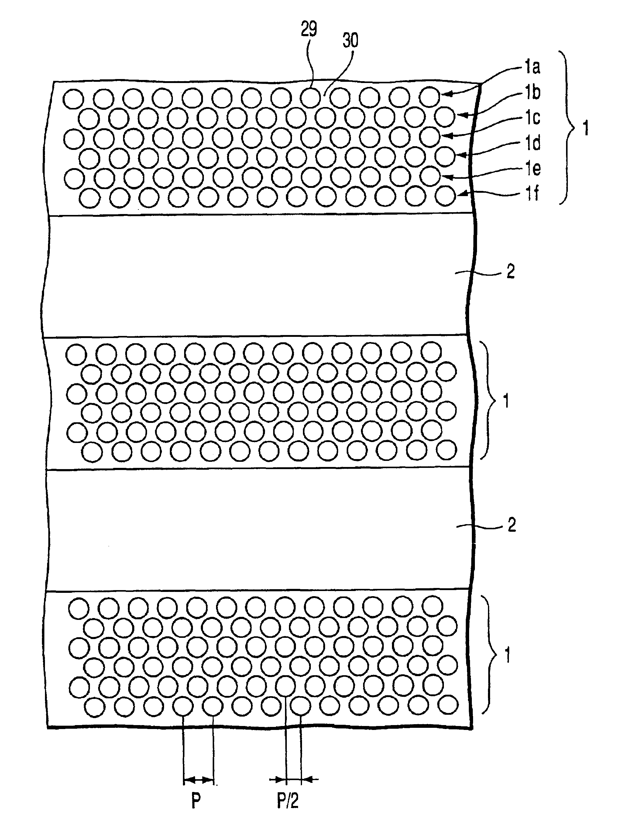
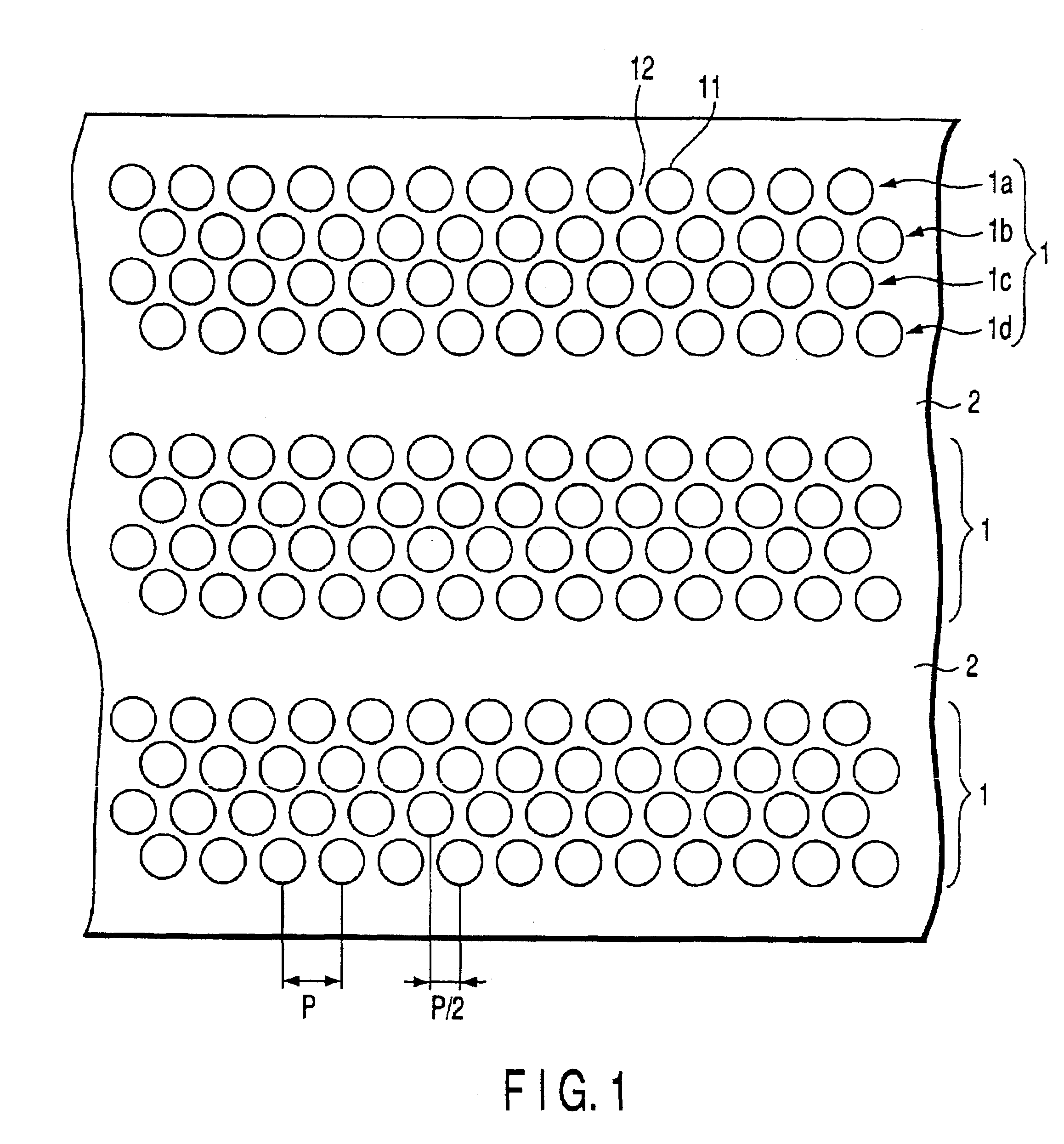
Image

Examples
example 1
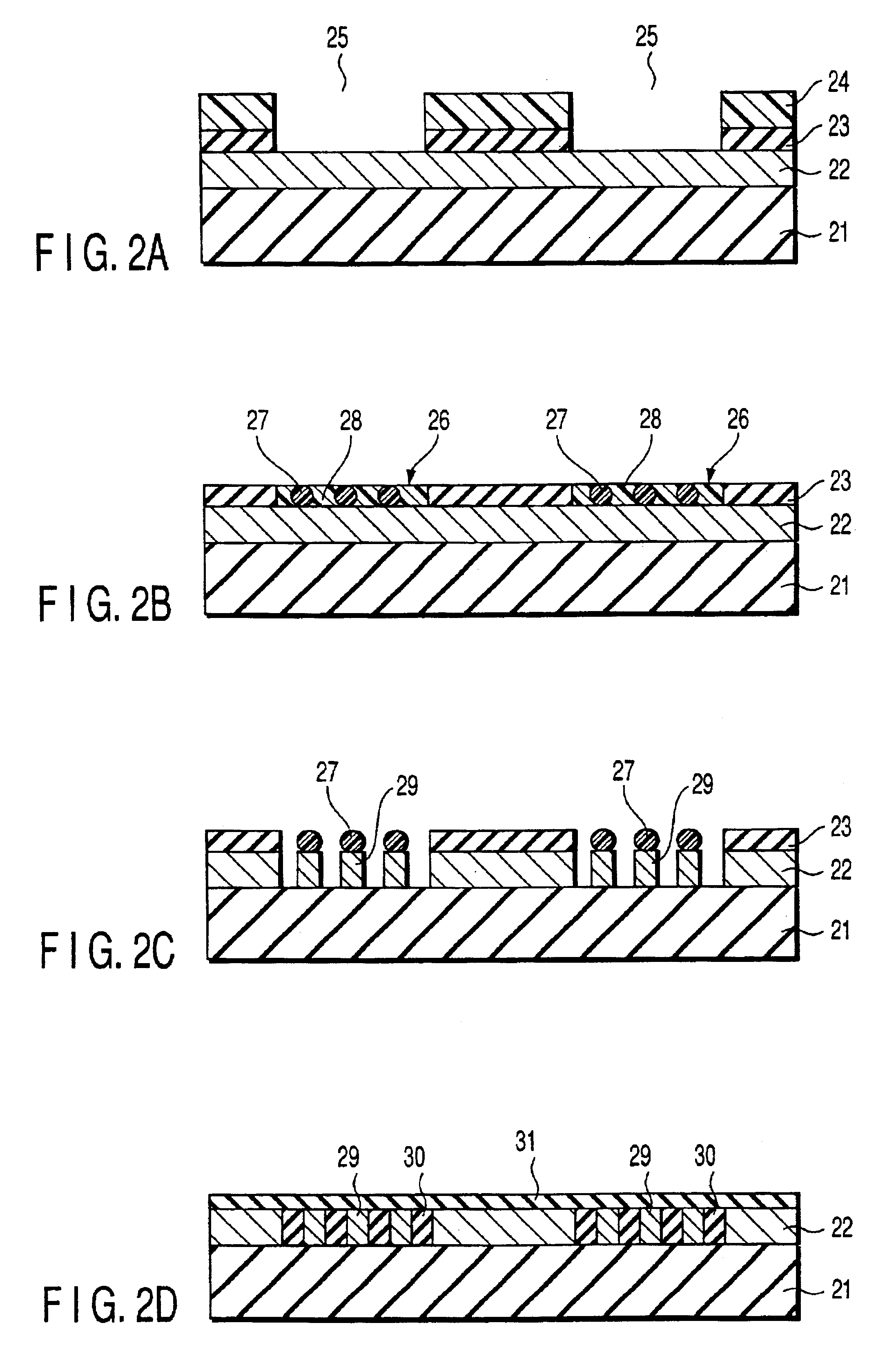
[0115]In this Example, a recording track band is formed by regularly arraying a block copolymer in a groove region formed on a substrate. A method of manufacturing a magnetic recording medium for this Example will now be described with reference to FIGS. 2A to 2D.
[0116]As shown in FIG. 2A, a groove structure is formed on a substrate as follows. Specifically, a magnetic layer 22 is formed by forming a Pd underlayer having a thickness of about 30 nm and a layer of a perpendicular magnetic recording material of Co—Cr—Pt having a thickness of about 50 nm on a glass disk substrate 21 having a diameter of 2.5 inches, followed by forming a SiO2 film 23 having a thickness of about 50 nm on the magnetic layer 22. Then, a resist film 24 is formed on the SiO2 film 23 by spin coating. Further, the resist film 24 is processed by optical lithography so as to form a resist pattern that is shaped such that a spiral groove 25 having a width of about 200 nm is defined by a convex portion having a wid...
example 2
[0121]In this Example, a recording track band is formed by regularly arraying a block copolymer in a band region containing a specified chemical substance formed on a substrate.
[0122]In the first step, a magnetic layer is formed on a substrate as in Example 1, followed by forming a SiO2 film having a thickness of about 10 nm on the magnetic layer and subsequently forming a resist film on the SiO2 film. As in Example 1, the resist film is processed by optical lithography so as to form a resist pattern such that a spiral groove having a width of about 200 nm is defined by a convex portion having a width of about 200 nm. After the surface of the exposed SiO2 film is subjected to hydrophobic treatment with octadecyltrimethoxysilane, followed by removing the resist pattern. As a result, formed on the surface of the SiO2 film are a hydrophilic band region (isolation region) which is not subjected to the hydrophobic treatment and a hydrophobic band region (recording track band) modified by...
example 3
[0126]A glass substrate is spin coated with a resist film containing a novolak resin as a base resin. The resist film is processed by optical lithography and development with a TMAH aqueous solution, followed by baking the resist film at 150° C. to cure the resin so as to form a resist pattern such that a spiral groove having a width of about 200 nm is defined by a convex portion having a width of about 200 nm and a height of about 40 nm.
[0127]Prepared is a solution by dissolving 2 parts by weight of polystyrene (PS)-polymethyl methacrylate (PMMA) block copolymer (PS having a molecular weight Mw of 65,000, PMMA having a molecular weight Mw of 13,500, and Mw / Mn being 1.0) in ethyl cellosolve acetate. The substrate is spin coated with the solution thus prepared so as to fill the groove regions between the resist patterns with the block copolymer. Then, the substrate is annealed so as to regularly array the block copolymer. As a result, formed is a structure in which island-like PMMA p...
PUM
| Property | Measurement | Unit |
|---|---|---|
| width | aaaaa | aaaaa |
| size | aaaaa | aaaaa |
| size | aaaaa | aaaaa |
Abstract
Description
Claims
Application Information