Three dimensional microfabrication

Inactive Publication Date: 2005-12-20
MASSACHUSETTS INST OF TECH
View PDF2 Cites 106 Cited by
  • Summary
  • Abstract
  • Description
  • Claims
  • Application Information

AI Technical Summary

Benefits of technology

[0007]In one aspect, the method for making three dimensional structures according to the invention includes providing a template having at least two conductive regions separated by a non-conductive region. The template is disposed in an electrolyte in an electrodeposition cell and a voltage is established between one of the conductive regions and an electrode in the cell. Material is deposited on the one of the conductive regions conducted to the voltage and subsequently bridges to the other conductive region so that material deposition contin

Problems solved by technology

Making three-dimensional (3-D) micromachined objects is difficult using current techniques; there are few alternatives to using a large number process steps and photolithographic masks.
Much of the published work tha

Method used


Image

  • Three dimensional microfabrication
  • Three dimensional microfabrication
  • Three dimensional microfabrication

Examples


Embodiment Construction

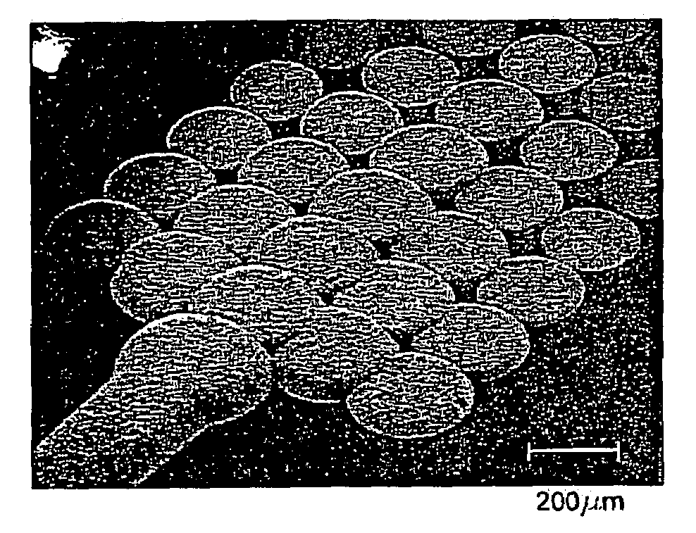
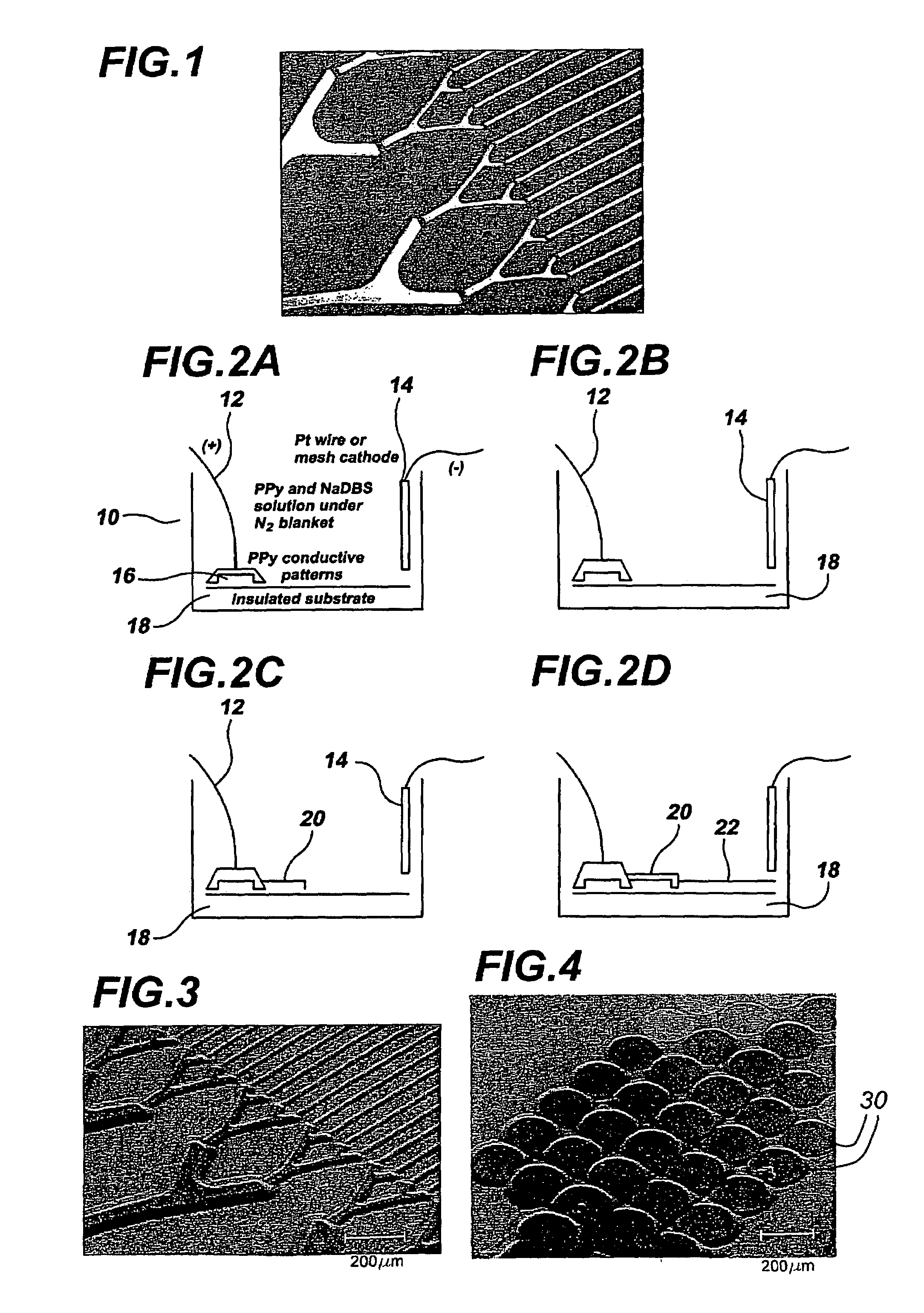
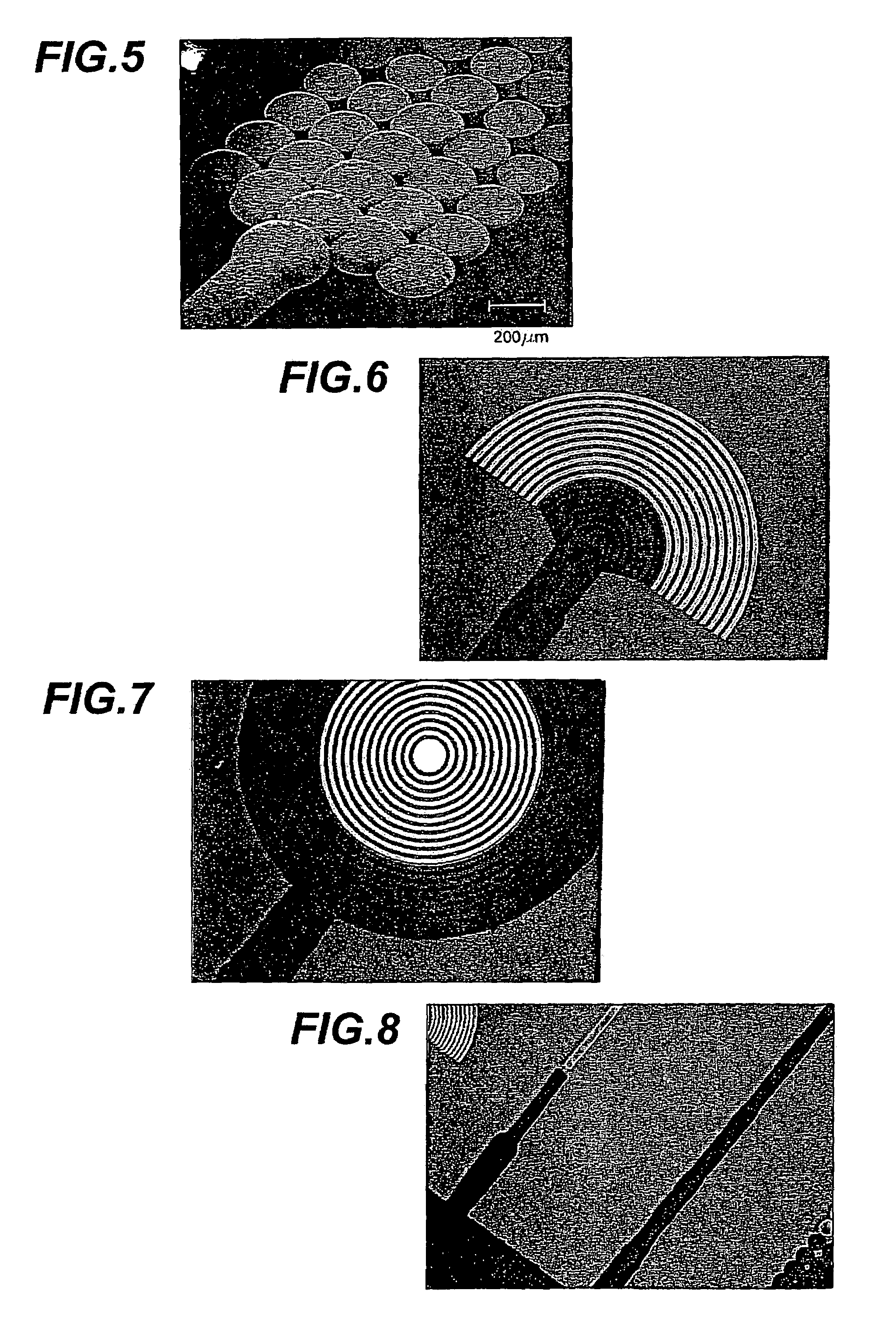
[0024]The present invention is a new approach to generate 3D microfabricated structures using very few steps and a single photolithographic mask. The approach relies on a conductive template that can be produced using conventional lift-off microfabrication, or by other means such as self-assembly or printing followed by an electrodeposition step to produce the full structure. The design of the conductive template determines the full 3D structure. Gaps, or non-conductive areas, between conductive regions of the template are intentionally introduced. As material is deposited it expands both vertically and horizontally; the horizontal expansion bridges the spaces between the conductive regions. Once that space is bridged the electrodeposited material forms an electrical connection with the new region and deposition then continues not only on the existing structure but on the newly connected region as well.

[0025]FIGS. 2a, b, c, and d are schematic illustrations of an embodiment of appar...


PUM

PropertyMeasurementUnit
Lengthaaaaaaaaaa
Structureaaaaaaaaaa
Solubility (mass)aaaaaaaaaa

Abstract

Method for making three-dimensional structures. A template is provided having at least two conductive regions separated by a non-conductive region. The template is disposed in an electrolyte in an electrodeposition cell and a voltage is established between one of the conductive regions and an electrode in the cell. Material is deposited on the one of the conductive regions connected to the voltage and subsequently bridges to the other conductive region with material deposition continuing on both of the at least two regions. The non conductive region may be a gap and the gap dimension is selected to regulate height differences between the at least two conductive regions.

Description

THREE DIMENSIONAL MICROFABRICATION[0001]This application claims priority to provisional application Ser. No. 60 / 452,891 filed Mar. 7, 2003 entitled “Methods and Uses for Simple Three-Dimensional Microfabrication,” the contents of which are incorporated herein by reference.BACKGROUND OF THE INVENTION[0002]This invention relates to the three-dimensional microfabrication of structures and more particularly to the microfabrication of electrodeposited structures.[0003]Making three-dimensional (3-D) micromachined objects is difficult using current techniques; there are few alternatives to using a large number process steps and photolithographic masks. An example is the formation of poly (dimethyl siloxane) (PDMS) replicas of micromachined master patterns for soft lithography and for the creation of microfluidic devices. See, A. Kumar, N. L. Abbott, H. A. Biebuyck, E. Kim, G. M. Whitesides, Acc. Chem Res. 1995, 28, 219; E. Kim, Y. Xia, G. M. Whitesides, J. Am. Chem. Soc. 1996, 118, 5722; a...

Claims


Application Information

Patent Timeline
IPC IPC(8): C25D1/00C25D1/10C25D3/38C25D5/02C25D5/16G02B6/124G02B6/13H01L21/288H01L21/768
CPCB81C99/0095C25D1/00C25D1/10C25D3/38C25D5/022C25D5/16G02B6/124G02B6/13H01L21/2885H01L21/76838C25D1/003
Inventor GEORGE, PAUL M.LANGER, ROBERT S.LAVAN, DAVID A.
Owner MASSACHUSETTS INST OF TECH
Why Eureka
Try Eureka