Magnetic recording/reproducing apparatus and electric apparatus

a technology of which is applied in the field of magnetic tape recording/reproducing apparatus and electric apparatus, can solve the problems of increasing the production cost of the input gear b>162/b> having the specific shape, increasing the production cost and simplifying the structure of the magnetic tape apparatus. , to achieve the effect of reducing the production cost and simplifying the structure of the magnetic tape apparatus

Inactive Publication Date: 2005-12-27
FUNAI ELECTRIC CO LTD
View PDF2 Cites 9 Cited by
  • Summary
  • Abstract
  • Description
  • Claims
  • Application Information

AI Technical Summary

Benefits of technology

[0012]This invention has been accomplished to solve the problem as described above. An object of this invention is to provide a magnetic recording / reproducing apparatus and an electric apparatus provided with an idler mechanism that is relatively simple in structure and can be reduced in cost.
[0018]In this way, when the drive gear rotates, the rotating torque for moving the swing gear is generated in the rotating direction of the drive gear at the contact area between the drive gear and swing gear. By continuously rotating the drive gear so that the contact area between the swing gear and the drive gear moves toward the one reel gear, the state where the swing gear is in contact with the one reel gear can be kept. Further, likewise, by continuously rotating the drive gear so that the contact area between the swing gear and drive gear moves toward the intermediate gear, the state where the swing gear is in contact with the intermediate gear can be kept.
[0021]Accordingly, in accordance with this invention, without using a spring for bringing the swing gear into contact with the swing arm, and without forming the shape of the gear in a specific shape, the idler mechanism which is simple in structure and can be manufactured at low cost can be realized.
[0029]In this configuration, the size of the swing arm can be made smaller than the case where the swing gear is arranged at the center in the longitudinal direction of the swing arm. As a result, the idler mechanism can be made compact, and hence the magnetic recording / reproducing apparatus or electric apparatus can be downsized.
[0031]In this way, if the idler mechanism of the electric apparatus according to this invention is employed as a mechanism for changing the drive reel in the pair of reels (one reel and the other reel) for driving the magnetic tape cassette, simplifying structure of the magnetic tape apparatus as an electric apparatus using the magnetic tape cassette and reduction in its production cost can be realized.

Problems solved by technology

However, the conventional idler mechanism described above presents the following problem.
Specifically, the idler mechanism in which the spring is arranged to press the idler gear on the swing arm has a complicated structure and requires an increased number of components because of the spring as a separate component.
Therefore, the production cost of the magnetic tape apparatus is increased.
Therefore, the production cost of the input gear 162 having the specific shape may become higher than that of a usual gear.
As a result, the production cost of the entire magnetic tape apparatus cannot be reduced sufficiently.

Method used


Image

  • Magnetic recording/reproducing apparatus and electric apparatus
  • Magnetic recording/reproducing apparatus and electric apparatus
  • Magnetic recording/reproducing apparatus and electric apparatus

Examples


Embodiment Construction

[0042]Now referring to the drawings, an explanation will be given of the mode for carrying out this invention. Incidentally, in the following drawings, like reference numerals refer to like parts.

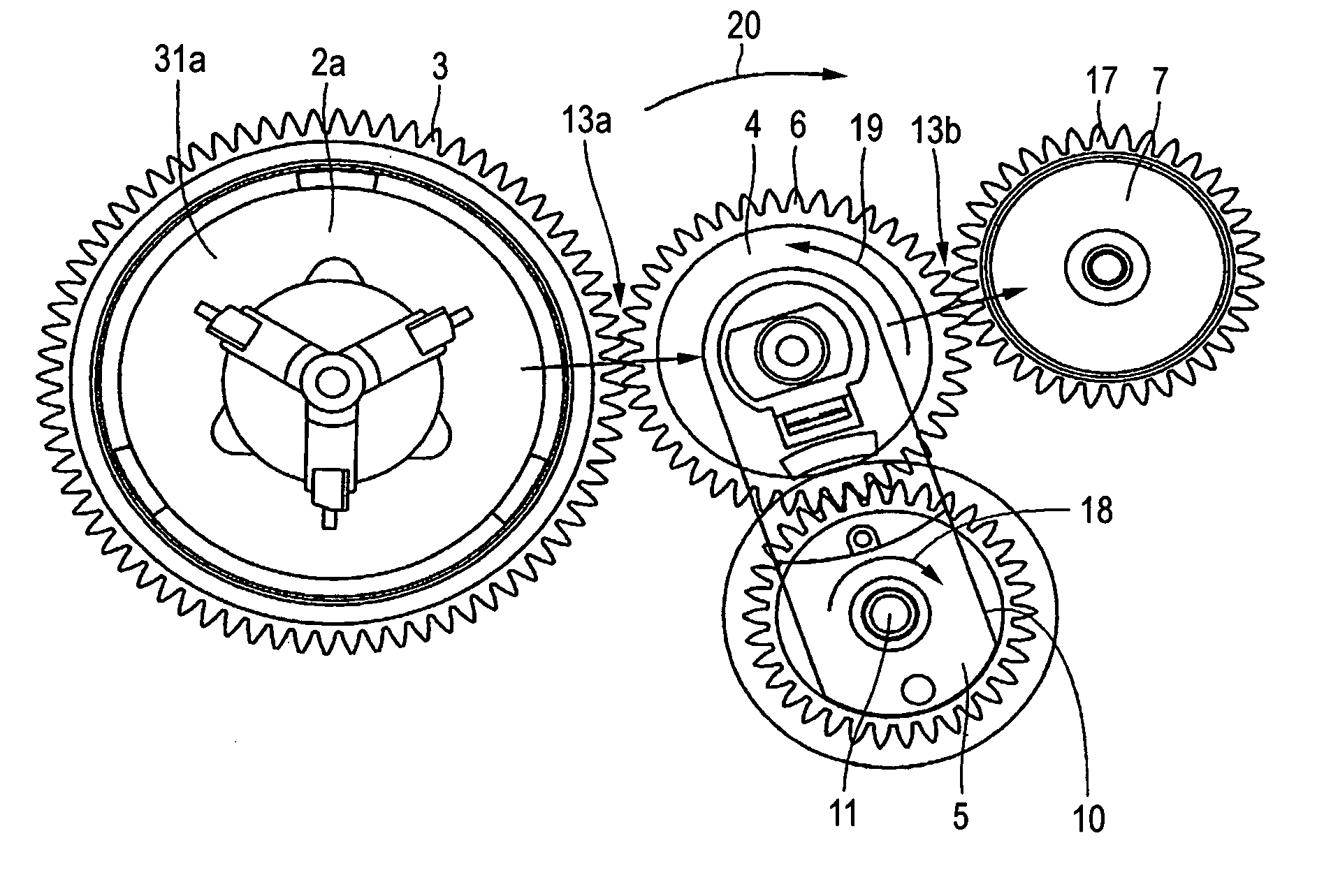
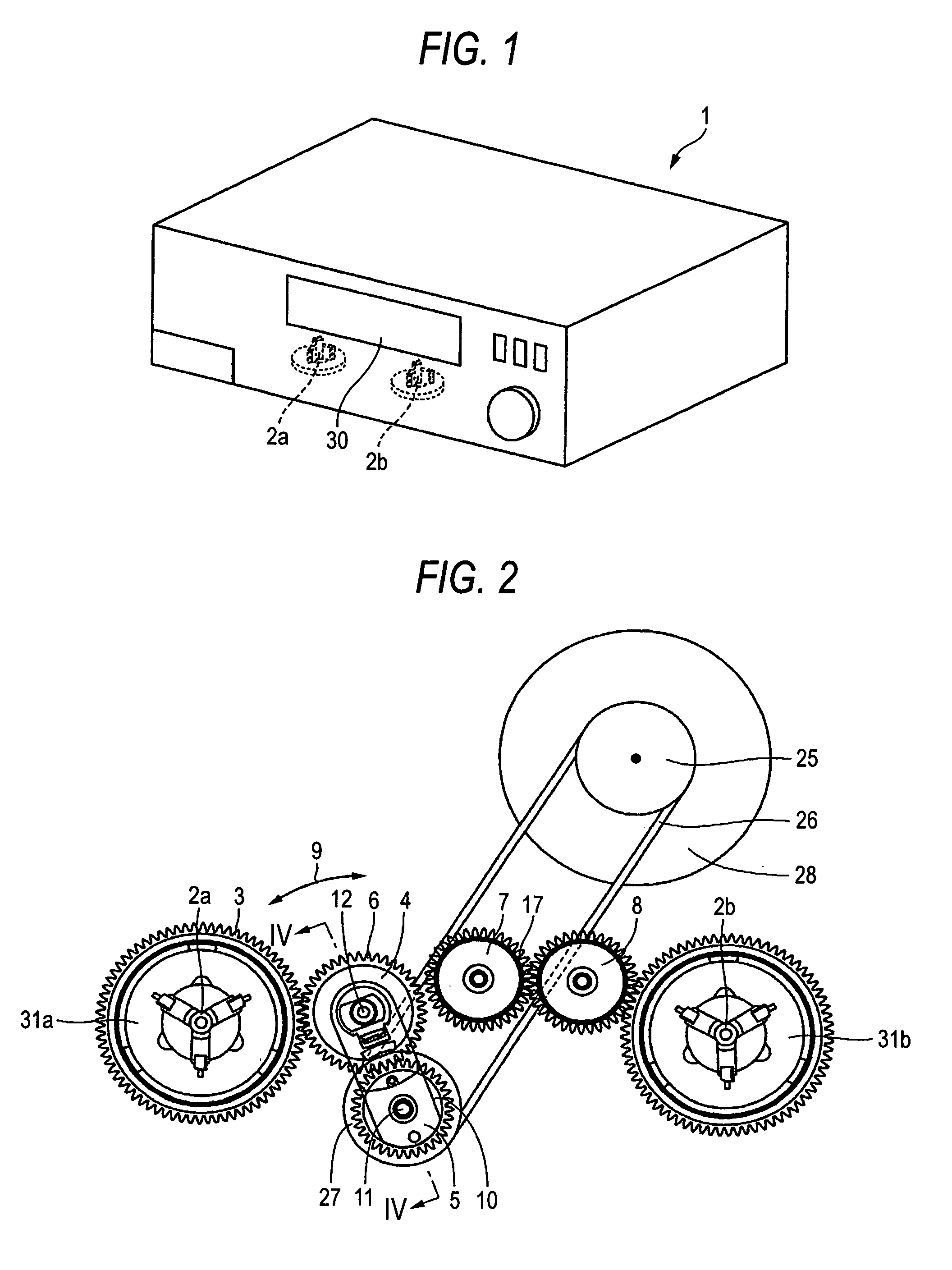
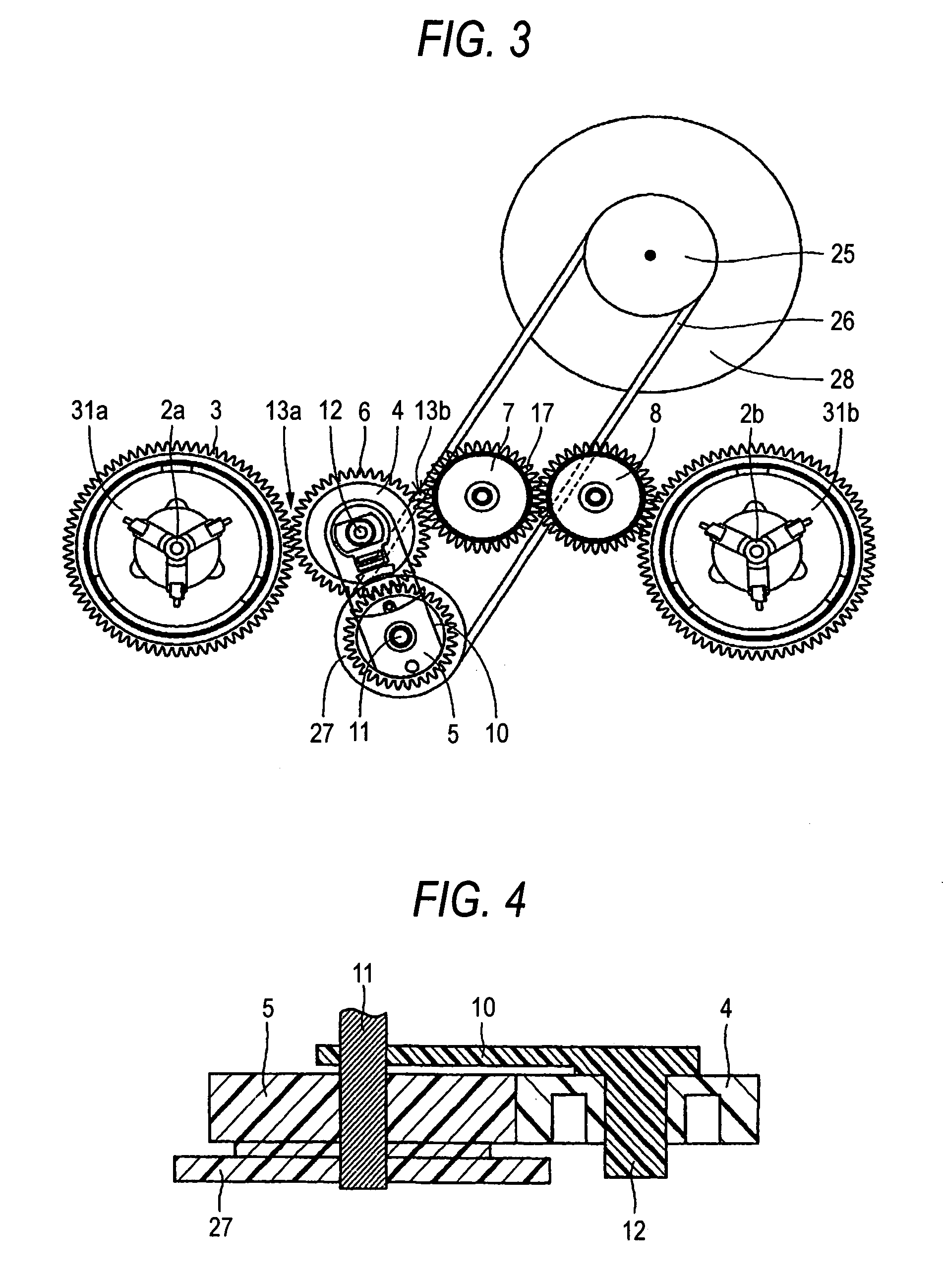
[0043]FIG. 1 is a perspective schematic view of a video cassette recorder according to this invention. FIG. 2 is a schematic view showing the idler mechanism for driving the reels incorporated in the video cassette recorder shown in FIG. 1. FIG. 3 is a schematic view for explaining the feature of the idler mechanism shown in FIG. 2. FIG. 4 is a sectional schematic view of a swing portion of the idler mechanism taken along line IX—IX. Referring to FIGS. 1 to 4, the video cassette recorder according to this invention will be explained.

[0044]As shown in FIG. 1, a video cassette recorder 1 which is an embodiment of a magnetic recording / reproducing apparatus or electric apparatus according to this invention incorporates two reels 2a, 2b. These reels 2a, 2b serve to rotate normally and inversely ...


PUM

PropertyMeasurementUnit
swinging torqueaaaaaaaaaa
areaaaaaaaaaaa
friction resistanceaaaaaaaaaa

Abstract

A magnetic recording / reproducing apparatus or an electric apparatus includes a reel gear, an intermediate gear, a swing arm, an idler gear and an input gear. The swing arm, idler gear and input gear constitute an idler mechanism. The intermediate gear is arranged apart from the reel gear. The swing arm is arranged between the reel gear and the intermediate gear. The swing arm is swingable between the reel gear and the intermediate gear around a center axis. The idler gear is attached to the swing arm. The idler gear is continuously kept in contact with at least one of the reel gear and the intermediate gear. The input gear is rotatable about the center axis, and is brought into contact with the idler gear.

Description

BACKGROUND OF THE INVENTION[0001]1. Field of the Invention[0002]This invention relates to a magnetic recording / reproducing apparatus and an electric apparatus, and more particularly to a magnetic recording / reproducing apparatus and an electric apparatus which are simple in structure and capable of reducing their production cost.[0003]2. Description of the Related Art[0004]Conventionally, a magnetic tape apparatus such as a video cassette recorder is known as an example of magnetic recording / reproducing apparatus or an electric apparatus. The magnetic tape apparatus is provided with a pair of reels for forwardly and inversely rotating a pair of tape reels on a tape supply side and a tape take-up side, which are accommodated in a tape cassette. In order to change the rotating direction of the reels, an idler mechanism is employed. A structure of the idler mechanism is known in which an idler gear attached to a swing arm is displaced to swing between a first position where rotation is ...

Claims


Application Information

Patent Timeline
Patent Type & Authority Patents(United States)
IPC IPC(8): G11B15/32G11B15/44
CPCG11B15/32G11B15/444Y10T74/19614Y10T74/19619
Inventor TAKASAKA, DAISUKE
Owner FUNAI ELECTRIC CO LTD
Why Eureka
Try Eureka