Igniting operation mechanism of piezoelectric ignition firing rod

Inactive Publication Date: 2005-12-27
TOKAI
View PDF8 Cites 7 Cited by
  • Summary
  • Abstract
  • Description
  • Claims
  • Application Information

AI Technical Summary

Benefits of technology

[0008]The present utility lighter ignition actuation mechanism pushes the piezoelectric or other spark generating mechanism by movement of the actuation member in a predetermined direction to generating discharge current to produce a spark between discharge electrodes for igniting released fuel gas. Generally, the present invention features a smoothly increasing forc

Problems solved by technology

Operability is adversely affected if the actuation forces are increased too early or abruptly in the stroke, or too late so that to get to the desired maximum force, the spring rate must be so steep that the user feels wh

Method used


Image

  • Igniting operation mechanism of piezoelectric ignition firing rod
  • Igniting operation mechanism of piezoelectric ignition firing rod
  • Igniting operation mechanism of piezoelectric ignition firing rod

Examples


first embodiment

[0024](First Embodiment)

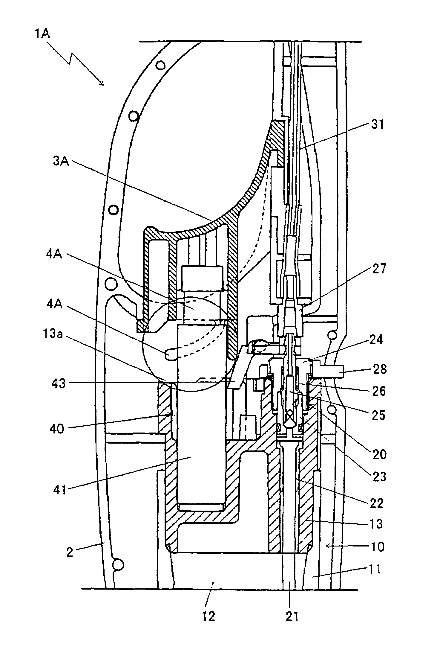
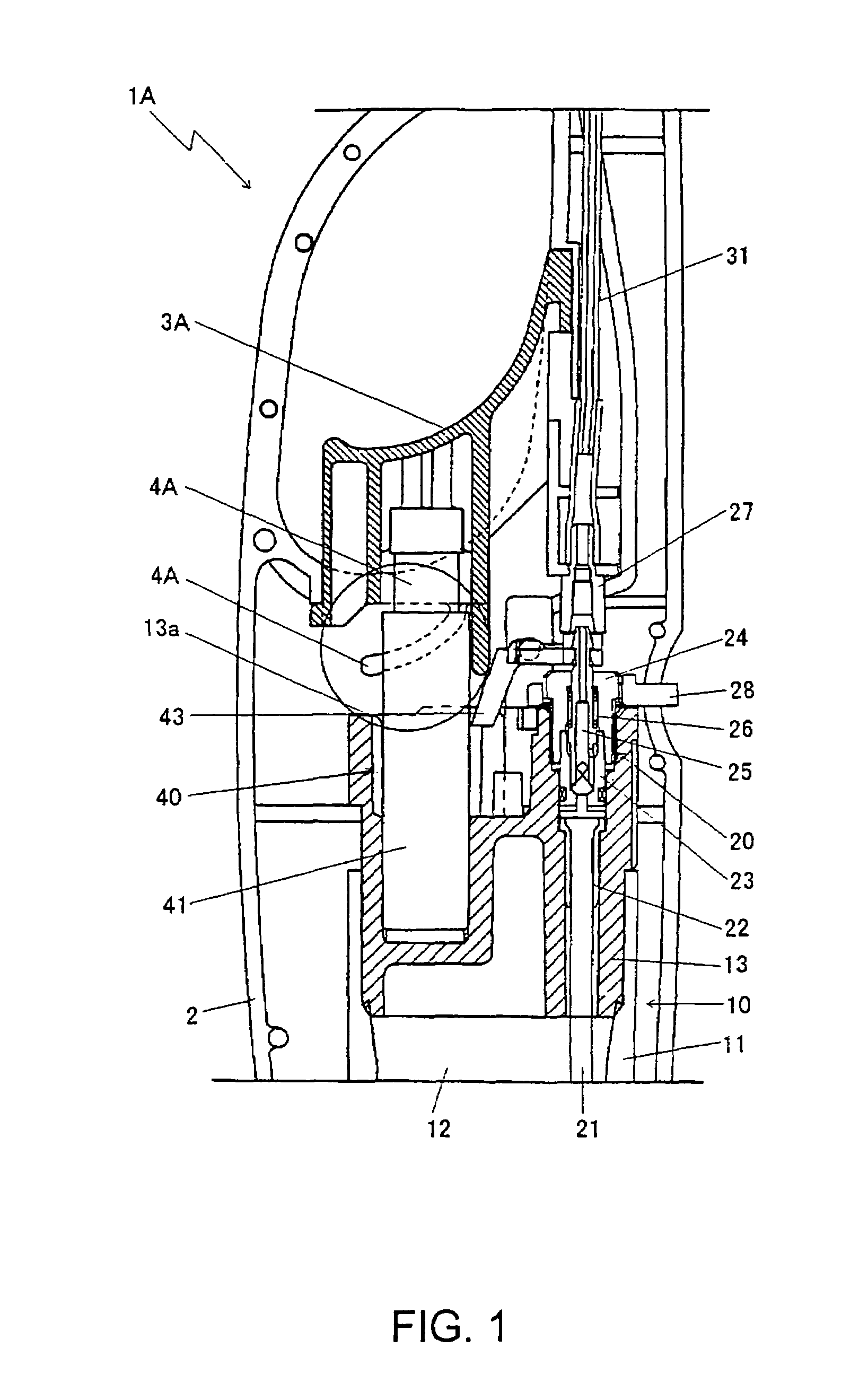
[0025]The utility lighter 1A as illustrated in FIG. 1 includes a split shell-type body case 2. A cap and a bottom plate (not shown) are assembled respectively to the tip and bottom of the body case 2.

[0026]A gas tank 10 is disposed inside the body case 2 for storing fuel gas. The gas tank 10 comprises a tank body 11 made by molding synthetic resin, a tank chamber 12 having a valve mechanism 20 to be described hereinafter secured to the upper surface of the tank body 11 for storing fuel gas such as butane gas inside the tank body 11, and an upper lid 13 made from synthetic resin for holding a piezoelectric mechanism 40 to be described hereinafter.

[0027]Secured to the upper lid 13 of the tank body 11 is the valve mechanism 20 for opening and closing the gas path from the gas tank 10, thereby controlling when and the amount of fuel gas emitted.

[0028]The valve mechanism 20 is a conventional design. It comprises a nozzle bottom 23 including the gas path and a valv...

second embodiment

[0041](Second Embodiment)

[0042]The second embodiment is the use of leaf springs separated from the actuation button as the resilient member for increasing the actuation load of the ignition operation in the way of the actuation stroke. The construction and operation of the other portions of the piezoelectric utility lighter are basically the same as those of the first embodiment. Accordingly, portions corresponding to those of the first embodiment have the same reference numerals. The following description of the second embodiment is directed to construction and operation unique to the second embodiment.

[0043]The piezoelectric utility lighter 1B of the second embodiment has a finger receiving actuation button 3B assembled to the end portion of the piezoelectric mechanism 40 capable of actuation from outside along the longitudinal direction of the body case 2 as the actuation member for ignition operation.

[0044]In order to increase the actuation load rate for ignition operation requi...


PUM


Abstract

The present invention provides an ignition actuation mechanism for the manual actuator of a spark producing device in a fuel gas lighter to increase the actuation force immediately before spark discharge without unreasonably increasing the actuation force at the initial stages of movement of the manual actuator to reduce that chances of inadvertent ignition by small children, but maintaining good operability for adult users. Movement of the manual actuator is always resisted by a first elastic member while a second elastic member is positioned to resist movement of the manual actuator at a maximum of 30N to 50N after 60% or more of the total movement of the manual actuator required to produce a spark has occurred. Preferably the second elastic member is one or more flexible fingers molded from polyacetal resin.

Description

FIELD OF INVENTION[0001]The present invention relates generally to a piezoelectric lighter, more specifically to an ignition mechanism for piezoelectric lighter with increased actuation load (resistance to actuation) for improving safety.BACKGROUND OF THE INVENTION[0002]There are conventional piezoelectric lighters as portable igniters. Such lighters each include a gas tank at one end of a relatively long body. A valve mechanism is provided at the top portion of the gas tank for opening or closing a gas path that extends from the valve mechanism towards a nozzle formed at the tip of the valve mechanism. Also, a piezoelectric mechanism is provided for generating discharge current in ganged relationship with a lever type manual actuation button operable from the exterior of the lighter. A lever mechanism is provided for opening the valve mechanism in connection with the current generation operation of the piezoelectric mechanism. Actuation of the actuation button opens the valve mecha...

Claims


Application Information

Patent Timeline
IPC IPC(8): F23Q2/16F23Q3/00F23Q2/28F23Q2/36
CPCF23Q2/164
Inventor ICHIKAWA, TOSHIHIROOZAWA, YOUICHI
Owner TOKAI
Why Eureka
Try Eureka