Integrated cervical-thoracic-lumbar spine MRI array coil

Active Publication Date: 2005-12-27
GENERAL ELECTRIC CO
View PDF23 Cites 59 Cited by
  • Summary
  • Abstract
  • Description
  • Claims
  • Application Information

AI Technical Summary

Problems solved by technology

The logic behind this application was that the required coverage of the spine area on the human body is extremely large and a single receive coil structure can not adequately provide the image quality necessary for clinical

Method used


Image

  • Integrated cervical-thoracic-lumbar spine MRI array coil
  • Integrated cervical-thoracic-lumbar spine MRI array coil
  • Integrated cervical-thoracic-lumbar spine MRI array coil

Examples


Embodiment Construction

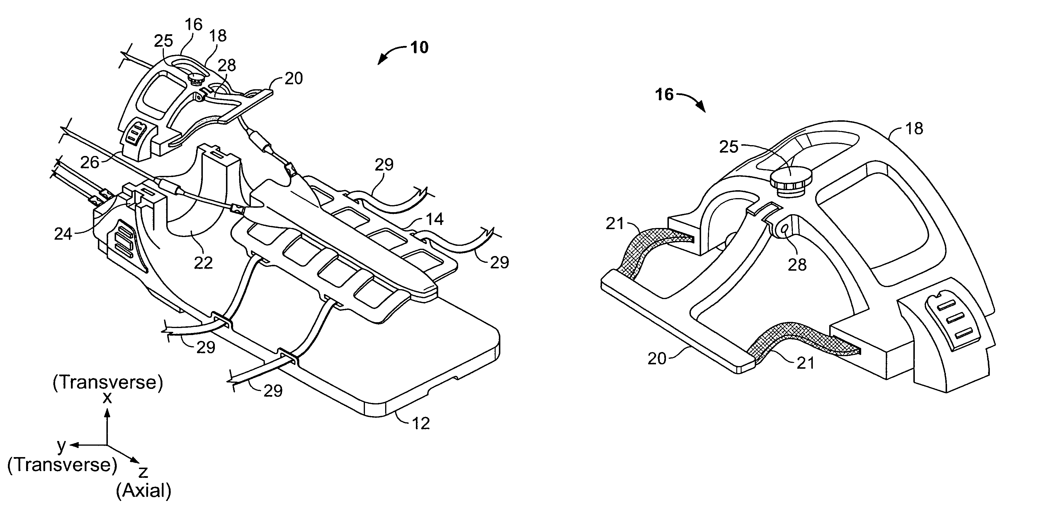
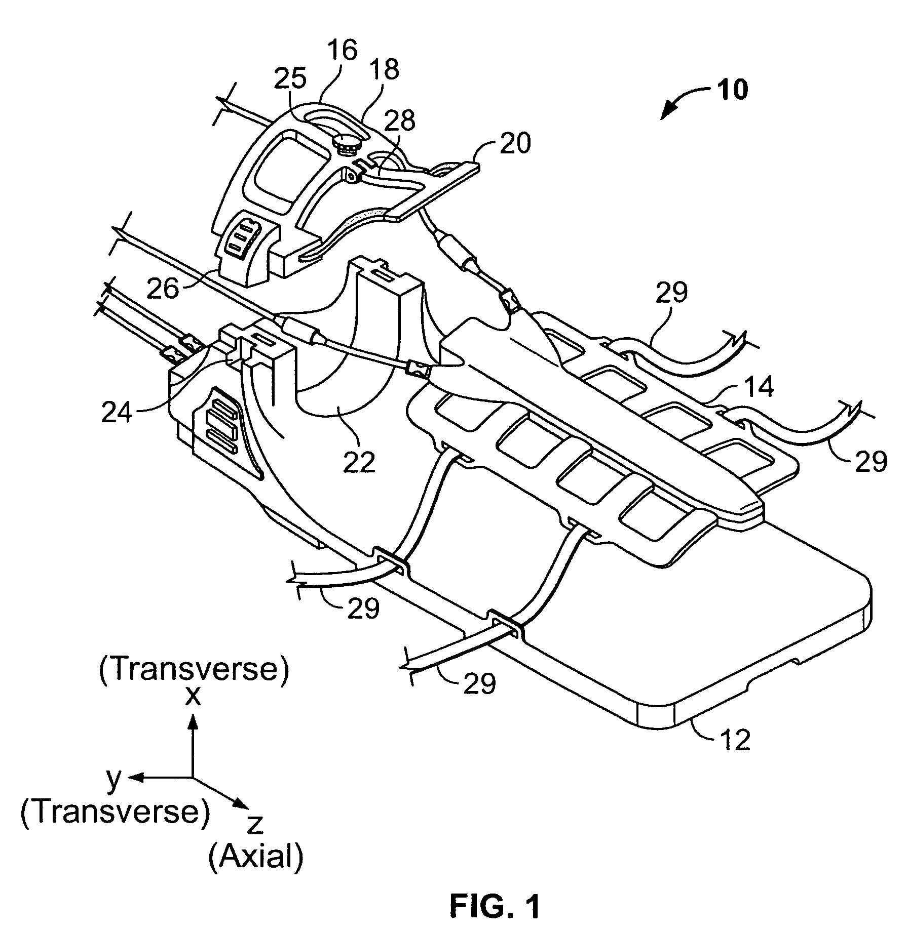
[0020]Referring to FIG. 1, a MRI coil array 10 for imaging the head, neck, upper chest and torso of a human patient includes a posterior array 12, an anterior torso coil 14 and an anterior head-neck-upper-chest array 16.

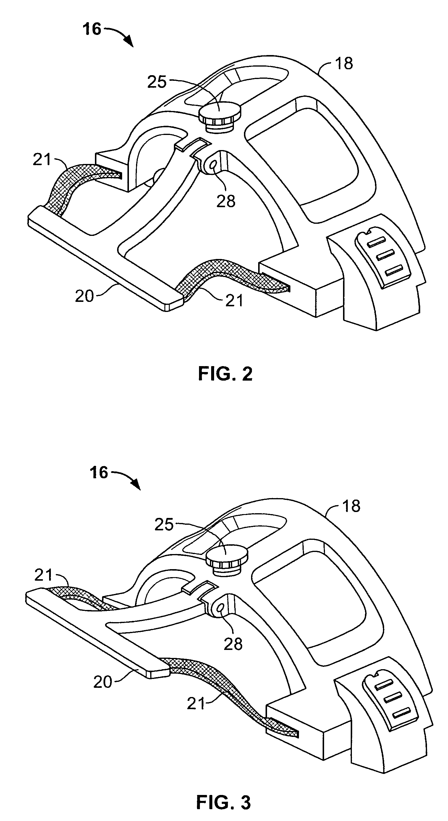
[0021]The head-neck-upper-chest array 16 includes a head portion 18 and a neck-upper-chest portion 20.

[0022]The posterior array 12 is in the form of a rigid structure the patient lays on. The patent's head is cradled in the area 22. After a patient lays on the array 12, the head portion 18 is mounted to the array 12 by the interlocking structures 24, 26 or by other suitable method. The neck-upper-chest portion 20 is attached to the head portion 18 by a hinging joint 28. It is also possible to make the portion of the posterior array 12 that is not involved in the mounting of the array 16 flexible. In addition, a rigid frame may be used in the array 12 and the coils themselves made flexibly conformable to the patient.

[0023]The neck-upper-chest portion 20 may be pivoted...


PUM


Abstract

A MRI array coil for imaging a human includes a posterior array, an anterior torso array and an anterior head-neck-upper-chest array. The head-neck-upper-chest array has a head portion mountable to the anterior array and a neck-upper-chest portion hingingly attached to the head portion.

Description

CROSS-REFERENCE TO RELATED APPLICATIONS[0001]This application claims priority to and the benefit of the filing date of U.S. Provisional application No. 60 / 423,505 filed Nov. 4, 2002 titled “integrated Cervical-Thoracic-Lumbar Spine Array Coil” and which is hereby incorporated by reference in its entirety.BACKGROUND OF THE INVENTION[0002]The present invention relates of magnetic resonance imaging (MRI) coils and, in particular, to array coils therefor.[0003]The phased array configuration for RF coils in magnetic resonance imaging was introduced by Roemer et al. as set forth in U.S. Pat. No. 4,825,162. Based on this design a set of surface coil loops are critically decoupled relative to each other and simultaneously receive the NMR signal which is generated in the imaging region that is excited by a dedicated volume coil. The signal from these surface coils is then reconstructed to generate an image which is multiple times larger that the size of each individual loop in the array. Acc...

Claims


Application Information

Patent Timeline
IPC IPC(8): A61B5/055G01R33/3415G01V3/00
CPCG01R33/3415
Inventor PETROPOULOS, LABROS SPIRIDONZOU, MARK XUEMINGZHENG, TSINGHUA
Owner GENERAL ELECTRIC CO
Why Eureka
Try Eureka