Non-intrusive coupling to shielded power cable

a shielded power cable and non-intrusive technology, applied in the direction of electric controllers, instruments, ignition automatic control, etc., can solve the problems of many inherent problems, adversely affecting the real and reactive power components provided by high-voltage cables, and prior art techniques that suffer from many inherent problems, so as to increase the inductance of power lines

Inactive Publication Date: 2005-12-27
UNWIRED BROADBAND INC
View PDF275 Cites 82 Cited by
  • Summary
  • Abstract
  • Description
  • Claims
  • Application Information

AI Technical Summary

Problems solved by technology

The prior art technique shown in FIG. 4 suffers from many inherent problems.
First, although not shown in FIG. 4, a lightning arrester device must be installed on both ends of high-voltage cable 315, thus adversely affecting the real and reactive power components provided by high-voltage cable 315.
Third, system 400 represents a dual-pole RLC circuit, and thus exhibits significant signal degradation over each frequency interval, a large as compared to a signal pole circuit.
Accordingly, when system 100 uses capacitive values at the lower end of the available range (e.g., 1 pf), attenuation of the signals is great and therefore undesirable.

Method used


Image

  • Non-intrusive coupling to shielded power cable
  • Non-intrusive coupling to shielded power cable
  • Non-intrusive coupling to shielded power cable

Examples


Embodiment Construction

Power-Based Communication System Overview

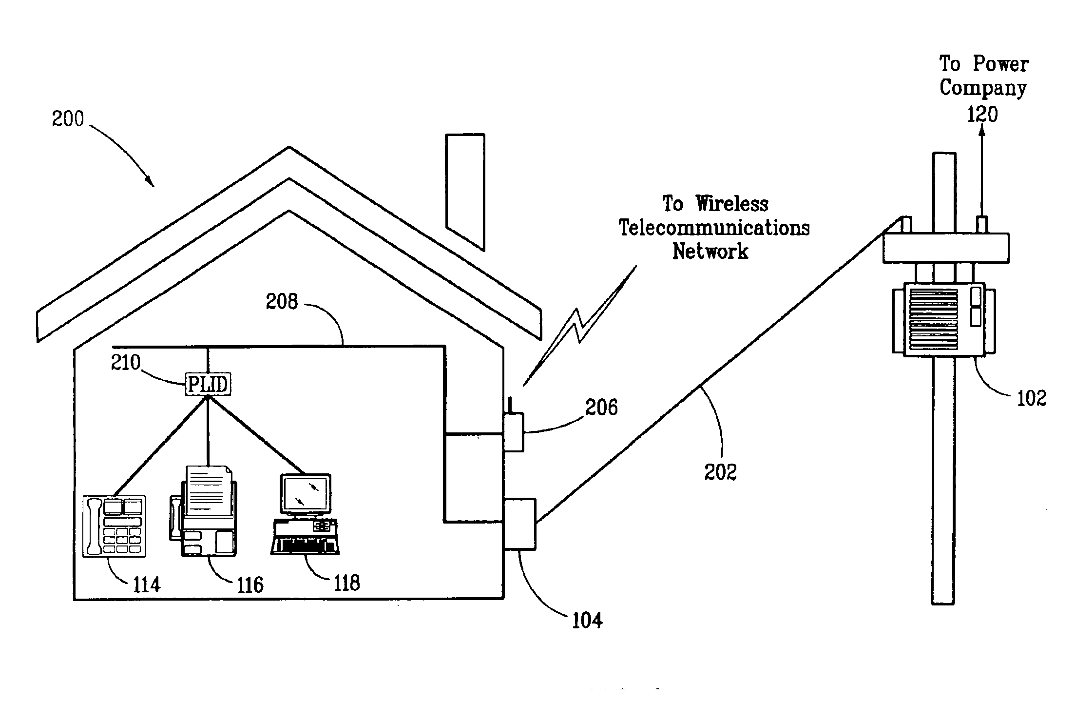
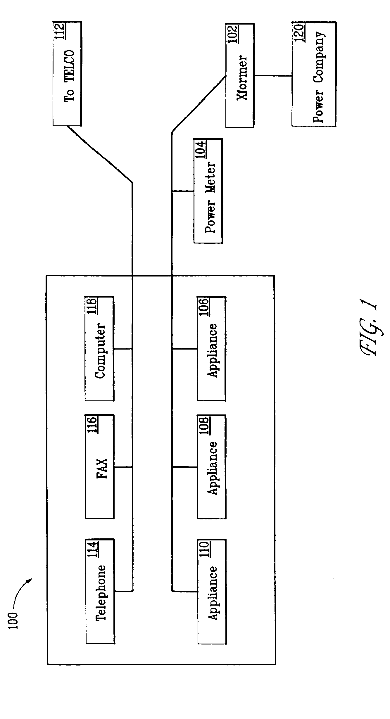
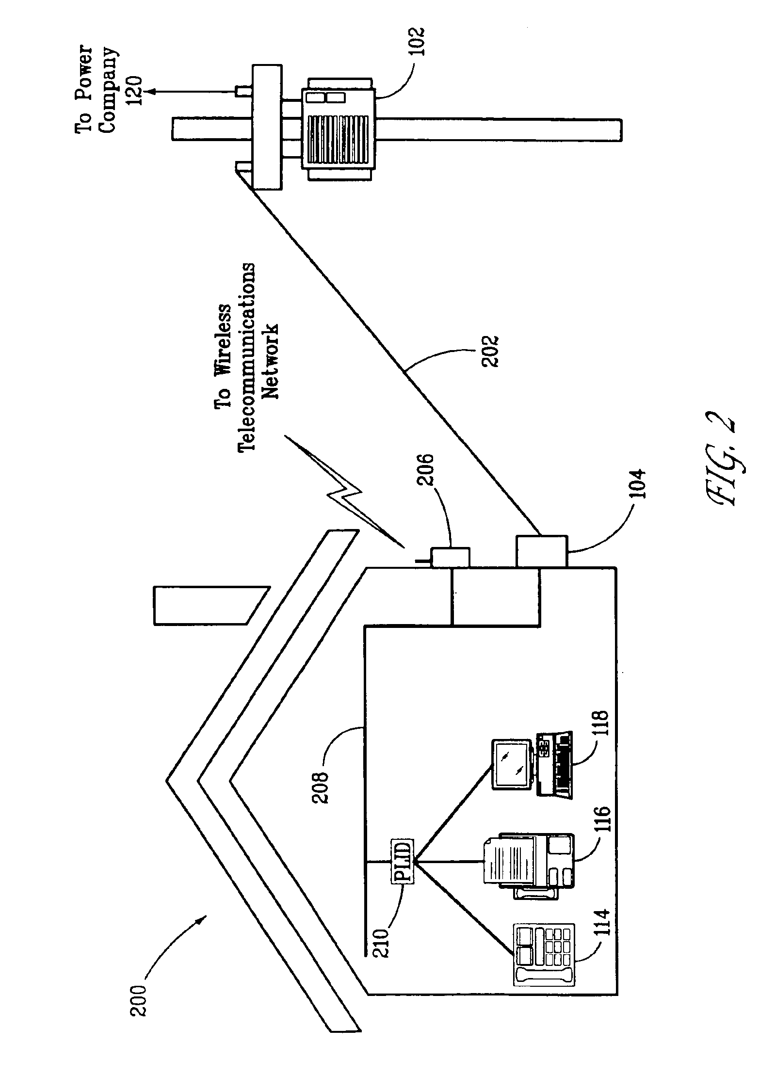
[0021]FIG. 1 is a block diagram of a typical electrical power system-based communication system 100. It should be appreciated that system 100 may include numerous other components, well known to those skilled in the art. However, the components depicted in system 100 and shown for the purposes of clarity and brevity, while providing a proper context for the invention.

[0022]As shown in FIG. 1, a power company 120 distributes power over its network to a power transformer 102. Power transformer 102 can serve several end users. Power transformer 102 provides stepped-down voltage to an electric power meter 104, which may be located with the end user. Power meter 102 is coupled to various appliances 106,108, and 110, which may represent any type of residential, commercial or industrial electrical equipment. Also, a telephone company 112 provides telecommunication wiring over its network directly to the end user. The telecommunication wiring may be ...


PUM


Abstract

The invention describes a method and a device for transporting a signal over a power line. The inventive method includes inducing an alternating current (AC) voltage from the power line, powering a transceiver device with the induced AC voltage, communicating the signal with the transceiver device via the power line. The method further may include transmitting and / or receiving the signal with an end user via the transceiver device. The transceiver device may be a fiber optic-based device that transmits data to the end user over non-metallic fiber optic links. The method may filter the induced AC voltage, and separately filter the signal.

Description

CROSS-REFERENCE TO RELATED APPLICATION[0001]This application claims priority under 35 U.S.C. § 119 (e) from provisional application No. 60 / 224,031, filed Aug. 9, 2000, which is incorporated by reference herein in its entirety.TECHNICAL FIELD[0002]The invention relates generally to non-intrusively coupling to shielded power cables. More specifically, the invention relates to coupling to power cables for the purpose of allowing the power cable to act as a data transmission medium.BACKGROUND OF THE INVENTION[0003]Transmitting data to end users has become the main focus of many technologies. Data networks provide the backbone necessary to communicate the data from one point to another. Of course, using existing networks, like the telecommunication networks, provides the benefit of not having to run new cables, which can create a great expense. On the other hand, using existing networks requires that the components that help carry the data conform to the requirements of the existing netw...

Claims


Application Information

Patent Timeline
Patent Type & Authority Patents(United States)
IPC IPC(8): H04B3/56H04M11/04
CPCH04B3/56H04B2203/5483
Inventor KLINE, PAUL A.
Owner UNWIRED BROADBAND INC
Why Eureka
Try Eureka